


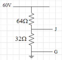
Find potential of J with respect to G.
\[\begin{align}
& \text{A}\text{. 40}V \\
& \text{B}\text{. 60}V \\
& \text{C}\text{. 20}V \\
& \text{D}\text{. 30}V \\
\end{align}\]
Answer
585.6k+ views
Hint: We have given a diagram for which we have to find the potential at node J. We can redraw the diagram in a simple way and then by analysing it we can find the voltage at node J. The node G is ground terminal. We will first find the current flowing through the circuit then by using it we can find the voltage at node J.
Formula used:
\[V=IR\]
Complete answer:
The given circuit can be redrawn as follows
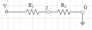
Here V is the main supply whose value is given as 60V. \[{{R}_{1}}\text{ and }{{R}_{2}}\]are the resistors connected in series between V and G, the ground terminal, their values are \[64\Omega \text{ and 32}\Omega \] respectively. Potential at the ground terminal is always zero.
Now, according to Ohm’s law, voltage is given as the product of current and resistance.
\[V=IR\]
We can rewrite the Ohm’s law for the current as
\[I=\dfrac{V}{R}\]
By using the above formula we can find the current flowing through the circuit. Here R will be equivalent to the resistance of \[{{R}_{1}}\text{ and }{{R}_{2}}\] and voltage, V is given 60V. As \[{{R}_{1}}\text{ and }{{R}_{2}}\]are connected in series therefore above equation will become
\[I=\dfrac{V}{{{R}_{1}}+{{R}_{2}}}\]
Substituting the values \[V=60V,{{R}_{1}}=64\Omega \text{ and }{{R}_{2}}=\text{32}\Omega \]we get
\[\begin{align}
& I=\dfrac{60}{64+\text{32}} \\
& I=\dfrac{60}{96} \\
& I=0.625A \\
\end{align}\]
As G is ground terminal, so voltage at node J with respect to G can be given as
\[{{V}_{J}}=I{{R}_{2}}\]
Substituting value of\[{{R}_{2}}\text{ and }I\], we calculated above we get
\[\begin{align}
& {{V}_{J}}=0.625\times 32 \\
& {{V}_{J}}=20V \\
\end{align}\]
Hence the potential at J with respect to G is 20V.
Correct option is C.
Note:
The above circuit is similar to Thevenin’s equivalent circuit where V is the input voltage and output is obtained across the J and G terminal. Hence voltage at J will be output voltage and it can be given directly by using Thevenin’s formula. Also note that the equivalent resistance for the resistors connected in series is given as the sum of the resistance of the resistors.
Formula used:
\[V=IR\]
Complete answer:
The given circuit can be redrawn as follows
Here V is the main supply whose value is given as 60V. \[{{R}_{1}}\text{ and }{{R}_{2}}\]are the resistors connected in series between V and G, the ground terminal, their values are \[64\Omega \text{ and 32}\Omega \] respectively. Potential at the ground terminal is always zero.
Now, according to Ohm’s law, voltage is given as the product of current and resistance.
\[V=IR\]
We can rewrite the Ohm’s law for the current as
\[I=\dfrac{V}{R}\]
By using the above formula we can find the current flowing through the circuit. Here R will be equivalent to the resistance of \[{{R}_{1}}\text{ and }{{R}_{2}}\] and voltage, V is given 60V. As \[{{R}_{1}}\text{ and }{{R}_{2}}\]are connected in series therefore above equation will become
\[I=\dfrac{V}{{{R}_{1}}+{{R}_{2}}}\]
Substituting the values \[V=60V,{{R}_{1}}=64\Omega \text{ and }{{R}_{2}}=\text{32}\Omega \]we get
\[\begin{align}
& I=\dfrac{60}{64+\text{32}} \\
& I=\dfrac{60}{96} \\
& I=0.625A \\
\end{align}\]
As G is ground terminal, so voltage at node J with respect to G can be given as
\[{{V}_{J}}=I{{R}_{2}}\]
Substituting value of\[{{R}_{2}}\text{ and }I\], we calculated above we get
\[\begin{align}
& {{V}_{J}}=0.625\times 32 \\
& {{V}_{J}}=20V \\
\end{align}\]
Hence the potential at J with respect to G is 20V.
Correct option is C.
Note:
The above circuit is similar to Thevenin’s equivalent circuit where V is the input voltage and output is obtained across the J and G terminal. Hence voltage at J will be output voltage and it can be given directly by using Thevenin’s formula. Also note that the equivalent resistance for the resistors connected in series is given as the sum of the resistance of the resistors.
Recently Updated Pages
Master Class 12 Economics: Engaging Questions & Answers for Success
Master Class 12 Physics: Engaging Questions & Answers for Success
Master Class 12 English: Engaging Questions & Answers for Success
Master Class 12 Social Science: Engaging Questions & Answers for Success
Master Class 12 Maths: Engaging Questions & Answers for Success
Master Class 12 Business Studies: Engaging Questions & Answers for Success
Trending doubts
Which are the Top 10 Largest Countries of the World?
What are the major means of transport Explain each class 12 social science CBSE
Draw a labelled sketch of the human eye class 12 physics CBSE
What is a transformer Explain the principle construction class 12 physics CBSE
Why cannot DNA pass through cell membranes class 12 biology CBSE
Differentiate between insitu conservation and exsitu class 12 biology CBSE