


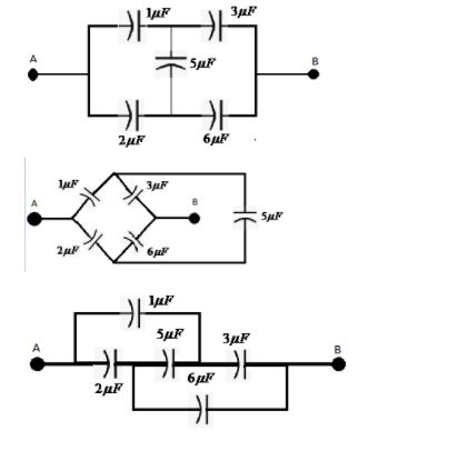
Convince yourself that parts a), b) and c) of the given figure are identical. Find the capacitance between the points A and B of the assembly.
Answer
590.4k+ views
Hint: In a circuit, two or more capacitors can be arranged in following ways:
They can be joined in series connection
They can be joined in parallel connection
They can be joined in a mixed connection which comprises both parallel and series connections.
The net or equivalent capacitance of the capacitors joined via series connection can be found through the following formula:
${{C}_{net}}=C+{{C}^{'}}$
The net or the equivalent capacitance of the capacitors joined via parallel connection can be found through following formula:
${{C}_{net}}=[\dfrac{{{C}_{1}}\times {{C}_{2}}}{{{C}_{1}}+{{C}_{2}}}]$
Complete step-by-step answer:
The capacitance of the given capacitors is as follows:
The capacitance of the capacitor 1: $1\mu F$
The capacitance of the capacitor 2: $2\mu F$
The capacitance of the capacitor 3: $3\mu F$
The capacitance of the capacitor 4: $6\mu F$
The capacitance of the capacitor 5: $5\mu F$
In the second and the third figure, the circuit branch containing the fifth capacitor lies in the between the two junctions which join the branches containing first and second capacitors and the branches containing third and fourth capacitors.
Thus, on the rearranging the circuit branches in the diagrams while keeping the connections intact, we can obtain the first circuit diagram.
Hence it is correct to say that the three circuit diagrams are all identical to one another.
Finding the net capacitance of the assembly:
We can observe that the ratios of the first capacitor to the second capacitor equals to the ratio of the third capacitor to the fourth capacitor, thereby establishing the equilibrium condition of the Wheatstone bridge such that no charge or current flows through the middle branch containing the fifth capacitor.
i.e. $\dfrac{{{C}_{1}}}{{{C}_{2}}}=\dfrac{{{C}_{3}}}{{{C}_{4}}}$
$\dfrac{1}{2}=\dfrac{3}{6}$
Hence the entire middle branch containing the fifth capacitor can be neglected completely while solving to find the net capacitance of the system.
Now it can be observed that the first and the third capacitors are in series connection with one another while the second and the fourth capacitors are in series connection with one another.
The resultant capacitance of the first pair is:
${{C}^{'}}={{[\dfrac{1}{{{C}_{1}}}+\dfrac{1}{{{C}_{3}}}]}^{-1}}$
$\Rightarrow {{C}^{'}}=[\dfrac{{{C}_{1}}\times {{C}_{3}}}{{{C}_{1}}+{{C}_{3}}}]$
$\Rightarrow {{C}^{'}}=[\dfrac{1\times 3}{1+3}]$
$\Rightarrow {{C}^{'}}=\dfrac{3}{4}$
The resultant capacitance of the second pair is:
$C={{[\dfrac{1}{{{C}_{2}}}+\dfrac{1}{{{C}_{4}}}]}^{-1}}$
$\Rightarrow C=[\dfrac{{{C}_{2}}\times {{C}_{4}}}{{{C}_{2}}+{{C}_{4}}}]$
\[\Rightarrow C=[\dfrac{2\times 6}{6+2}]\]
$\Rightarrow C=[\dfrac{12}{8}]$
The resultant capacitances of the 2 pairs are in parallel connection to one another.
Hence the net capacitance of the system will be:
${{C}_{net}}=C+{{C}^{'}}$
$\Rightarrow {{C}_{net}}=\dfrac{12}{8}+\dfrac{3}{4}$
$\Rightarrow {{C}_{net}}=\dfrac{6}{4}+\dfrac{3}{4}$
$\Rightarrow {{C}_{net}}=\dfrac{9}{4}\mu F=2.25\mu F$
Hence the equivalent capacitance of the given electrical circuit system is $2.25\mu F$.
Note: Capacitance of a given system can be defined as the ability of that system to store an electric charge.
This could be achieved by means of an electrical device, consisting of one or more pairs of conductors separated by an insulator. This device is known as a Capacitor.
The capacitance of a capacitor is directly proportional to charge stored by it and inversely proportional to voltage applied across it.
i.e. $C=\dfrac{Q}{V}$
Recently Updated Pages
Three beakers labelled as A B and C each containing 25 mL of water were taken A small amount of NaOH anhydrous CuSO4 and NaCl were added to the beakers A B and C respectively It was observed that there was an increase in the temperature of the solutions contained in beakers A and B whereas in case of beaker C the temperature of the solution falls Which one of the following statements isarecorrect i In beakers A and B exothermic process has occurred ii In beakers A and B endothermic process has occurred iii In beaker C exothermic process has occurred iv In beaker C endothermic process has occurred
Master Class 12 Social Science: Engaging Questions & Answers for Success
Master Class 12 Physics: Engaging Questions & Answers for Success
Master Class 12 Maths: Engaging Questions & Answers for Success
Master Class 12 Economics: Engaging Questions & Answers for Success
Master Class 12 Chemistry: Engaging Questions & Answers for Success
Three beakers labelled as A B and C each containing 25 mL of water were taken A small amount of NaOH anhydrous CuSO4 and NaCl were added to the beakers A B and C respectively It was observed that there was an increase in the temperature of the solutions contained in beakers A and B whereas in case of beaker C the temperature of the solution falls Which one of the following statements isarecorrect i In beakers A and B exothermic process has occurred ii In beakers A and B endothermic process has occurred iii In beaker C exothermic process has occurred iv In beaker C endothermic process has occurred
Master Class 12 Social Science: Engaging Questions & Answers for Success
Master Class 12 Physics: Engaging Questions & Answers for Success
Trending doubts
Which are the Top 10 Largest Countries of the World?
Draw a labelled sketch of the human eye class 12 physics CBSE
What are the major means of transport Explain each class 12 social science CBSE
Differentiate between homogeneous and heterogeneous class 12 chemistry CBSE
Sulphuric acid is known as the king of acids State class 12 chemistry CBSE
Why should a magnesium ribbon be cleaned before burning class 12 chemistry CBSE