


Calculate Power factor at the resonant frequency $f_0$.
Answer
587.7k+ views
Hint
The power factor is the cosine of the phase angle between voltage and current in an AC circuit. We will use the formula for the power factor in which phase angle is first determined. Resonance is a condition in an ac circuit according to which, capacitive reactance and inductive reactance are equal at a resonant frequency.
Complete step by step answer
We consider an LCR circuit consisting of a resistor, capacitor, and an inductor as shown in the figure.
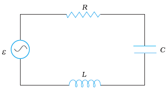
The impedance is in analogy with the resistance in the circuit and is represented as,
$Z=\sqrt {R^2+(X_C-X_L)^{2}}$
Here, XC represents capacitive reactance i.e. the resistance of the capacitor to the flow of alternating current and XL represents inductive reactance i.e. the resistance of the inductor to the flow of alternating current.
The phase angle is determined using impedance diagram such that,
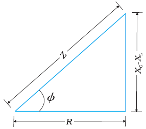
$cos \phi =\dfrac {R}{Z}$
Or $\cos \phi = \dfrac{R}{{\sqrt {{{\rm{R}}^2} + {{\left( {{{\rm{X}}_{\rm{C}}} - {{\rm{X}}_{\rm{L}}}} \right)}^2}} }}$
Power factor is the cosine of the phase angle implying that power factor is expressed by the relation,
Power factor $ = \dfrac{R}{{\sqrt {{{\rm{R}}^2} + {{\left( {{{\rm{X}}_{\rm{C}}} - {{\rm{X}}_{\rm{L}}}} \right)}^2}} }}$
Resonance is a common phenomenon among the ac circuit system that tends to oscillate at a frequency. At the resonance condition, the capacitive reactance and inductive reactance are equal i.e. ${{\rm{X}}_{\rm{C}}} = {{\rm{X}}_{\rm{L}}}$
For a non-inductive circuit that is an LCR circuit at resonance, the power factor is determined using,
$\cos \phi = \dfrac{R}{{\sqrt {{{\rm{R}}^2} + {{\left( {{{\rm{X}}_{\rm{C}}} - {{\rm{X}}_{\rm{L}}}} \right)}^2}} }}$
Since at resonance, ${{\rm{X}}_{\rm{C}}} = {{\rm{X}}_{\rm{L}}}$
∴ $\cos \phi = \dfrac{R}{R} = 1$
This implies that $\phi = 0^\circ $ and the power factor is one. Thus, maximum power is dissipated in a circuit through the resistance ‘R’ at resonance.
Therefore, $1$ is the required solution.
Note
This phenomenon of the resonance circuit is exhibited when both inductor and capacitor are present in the circuit. The resonant frequency is the oscillation of the system of an ac circuit at the condition of resonance.
The power factor is the cosine of the phase angle between voltage and current in an AC circuit. We will use the formula for the power factor in which phase angle is first determined. Resonance is a condition in an ac circuit according to which, capacitive reactance and inductive reactance are equal at a resonant frequency.
Complete step by step answer
We consider an LCR circuit consisting of a resistor, capacitor, and an inductor as shown in the figure.
The impedance is in analogy with the resistance in the circuit and is represented as,
$Z=\sqrt {R^2+(X_C-X_L)^{2}}$
Here, XC represents capacitive reactance i.e. the resistance of the capacitor to the flow of alternating current and XL represents inductive reactance i.e. the resistance of the inductor to the flow of alternating current.
The phase angle is determined using impedance diagram such that,
$cos \phi =\dfrac {R}{Z}$
Or $\cos \phi = \dfrac{R}{{\sqrt {{{\rm{R}}^2} + {{\left( {{{\rm{X}}_{\rm{C}}} - {{\rm{X}}_{\rm{L}}}} \right)}^2}} }}$
Power factor is the cosine of the phase angle implying that power factor is expressed by the relation,
Power factor $ = \dfrac{R}{{\sqrt {{{\rm{R}}^2} + {{\left( {{{\rm{X}}_{\rm{C}}} - {{\rm{X}}_{\rm{L}}}} \right)}^2}} }}$
Resonance is a common phenomenon among the ac circuit system that tends to oscillate at a frequency. At the resonance condition, the capacitive reactance and inductive reactance are equal i.e. ${{\rm{X}}_{\rm{C}}} = {{\rm{X}}_{\rm{L}}}$
For a non-inductive circuit that is an LCR circuit at resonance, the power factor is determined using,
$\cos \phi = \dfrac{R}{{\sqrt {{{\rm{R}}^2} + {{\left( {{{\rm{X}}_{\rm{C}}} - {{\rm{X}}_{\rm{L}}}} \right)}^2}} }}$
Since at resonance, ${{\rm{X}}_{\rm{C}}} = {{\rm{X}}_{\rm{L}}}$
∴ $\cos \phi = \dfrac{R}{R} = 1$
This implies that $\phi = 0^\circ $ and the power factor is one. Thus, maximum power is dissipated in a circuit through the resistance ‘R’ at resonance.
Therefore, $1$ is the required solution.
Note
This phenomenon of the resonance circuit is exhibited when both inductor and capacitor are present in the circuit. The resonant frequency is the oscillation of the system of an ac circuit at the condition of resonance.
Recently Updated Pages
Master Class 12 Economics: Engaging Questions & Answers for Success
Master Class 12 Physics: Engaging Questions & Answers for Success
Master Class 12 English: Engaging Questions & Answers for Success
Master Class 12 Social Science: Engaging Questions & Answers for Success
Master Class 12 Maths: Engaging Questions & Answers for Success
Master Class 12 Business Studies: Engaging Questions & Answers for Success
Trending doubts
Which are the Top 10 Largest Countries of the World?
What are the major means of transport Explain each class 12 social science CBSE
Draw a labelled sketch of the human eye class 12 physics CBSE
Why cannot DNA pass through cell membranes class 12 biology CBSE
Differentiate between insitu conservation and exsitu class 12 biology CBSE
Draw a neat and well labeled diagram of TS of ovary class 12 biology CBSE