


(a)Draw logic diagram of EX-OR and EX-NOR gate using NAND gate and proof it using Boolean equation and truth table.
(b)Draw a logic diagram of EX-OR and EX-NOR gate using NOR gate and proof it using Boolean equation and truth table.
Answer
588.9k+ views
Hint: An EX-OR gate is a digital logic gate which gives a true output when the number of inputs is odd only. Whereas, EX-NOR gate is just an EX-OR gate followed by a NOT gate which gives a true output only when the number of inputs is even. Simply put, EX-NOR gate gives an opposite output when compared to the output of EX-OR gate under the same input conditions.
Complete answer:
(a)
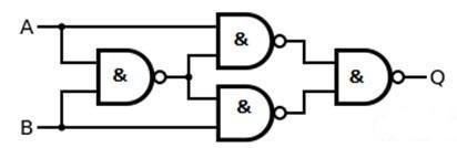
The logic diagram of EX-OR gate using NAND gate only is given as:
To prove it using the Boolean equation, we know Exclusive-OR gate is “ A or B but not BOTH”.
Let us prove the above expression.
In the first case consider,
\[A\text{ }=\text{ }0\] and\[B\text{ }=\text{ }0\] .
$\therefore A\oplus B=0\oplus 0=0.\overline{0}+\overline{0}.0=0.1+1.0=0$
In the second case consider,
\[A\text{ }=\text{ }0\] and\[B\text{ }=\text{ }1\] .
$\therefore A\oplus B=0\oplus 1=0.\overline{1}+\overline{0}.1=0.0+1.1=1$
In third case consider,
\[A\text{ }=\text{ }1\] and\[B\text{ }=\text{ }0\] .
$\therefore A\oplus B=1\oplus 0=1.\overline{0}+\overline{1}.0=1.1+0.0=1$
In fourth case consider,
\[A\text{ }=\text{ }1\] and\[B\text{ }=\text{ }1\] .
$\therefore A\oplus B=1\oplus 1=1.\overline{1}+\overline{1}.1=1.0+0.1=0$
So, it is proved that the Boolean expression for A ⊕ B is $A\overline{B}+\overline{A}B$ , as this Boolean expression satisfied all output states with respect to an XOR gate’s inputs conditions.
Proof using truth table:
Thus, it is proved using the Truth Table that EX-OR gate gives true output when the number of inputs is odd.
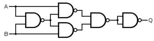
The logic diagram of EX-NOR gate using NAND gate is given as:
To proof it using Boolean equation, we know Exclusive-NOR gate is “$A\odot B$”
In the first case consider,
\[A\text{ }=\text{ }0\] and\[B\text{ }=\text{ }0\] .
$\therefore A\odot B=AB+\overline{A}\overline{B}=0.0+\overline{0}.\overline{0}=0.0+1.1=1$
In the second case consider,
\[A\text{ }=\text{ }0\] and\[B\text{ }=\text{ }1\] .
$\therefore A\odot B=AB+\overline{A}\overline{B}=0.1+\overline{0}.\overline{1}=0.1+1.0=0$
In third case consider,
\[A\text{ }=\text{ }1\] and\[B\text{ }=\text{ }0\] .
$\therefore A\odot B=AB+\overline{A}\overline{B}=1.0+\overline{1}.\overline{0}=1.0+0.1=0$
In fourth case consider,
\[A\text{ }=\text{ }1\] and\[B\text{ }=\text{ }1\] .
$\therefore A\odot B=AB+\overline{A}\overline{B}=1.1+\overline{1}.\overline{1}=1.1+0.0=1$
Hence, it is proved that EX-NOR gate is A ⊙ B .
Proof using truth table:
Thus, it is proved using the Truth Table that EX-NOR gate gives true output when the number of inputs is even.
(b)
The logic diagram of EX-OR gate using NOR gate only is given as:

To prove it using the Boolean equation, we know Exclusive-OR gate is “ A or B but not BOTH”.
Let us prove the above expression.
In the first case consider,
\[A\text{ }=\text{ }0\] and\[B\text{ }=\text{ }0\] .
$\therefore A\oplus B=0\oplus 0=0.\overline{0}+\overline{0}.0=0.1+1.0=0$
In the second case consider,
\[A\text{ }=\text{ }0\] and\[B\text{ }=\text{ }1\] .
$\therefore A\oplus B=0\oplus 1=0.\overline{1}+\overline{0}.1=0.0+1.1=1$
In third case consider,
\[A\text{ }=\text{ }1\] and\[B\text{ }=\text{ }0\] .
$\therefore A\oplus B=1\oplus 0=1.\overline{0}+\overline{1}.0=1.1+0.0=1$
In fourth case consider,
\[A\text{ }=\text{ }1\] and\[B\text{ }=\text{ }1\] .
$\therefore A\oplus B=1\oplus 1=1.\overline{1}+\overline{1}.1=1.0+0.1=0$
So, it is proved that the Boolean expression for A ⊕ B is $A\overline{B}+\overline{A}B$ , as this Boolean expression satisfied all output states with respect to an XOR gate’s inputs conditions.
Proof using truth table:
Thus, it is proved using the Truth Table that EX-OR gate gives true output when the number of inputs is odd.
The logic diagram of EX-NOR gate using NOR gate is given as:

To proof it using Boolean equation, we know Exclusive-NOR gate is “$A\odot B$”
In the first case consider,
\[A\text{ }=\text{ }0\] and\[B\text{ }=\text{ }0\] .
$\therefore A\odot B=AB+\overline{A}\overline{B}=0.0+\overline{0}.\overline{0}=0.0+1.1=1$
In the second case consider,
\[A\text{ }=\text{ }0\] and\[B\text{ }=\text{ }1\] .
$\therefore A\odot B=AB+\overline{A}\overline{B}=0.1+\overline{0}.\overline{1}=0.1+1.0=0$
In third case consider,
\[A\text{ }=\text{ }1\] and\[B\text{ }=\text{ }0\] .
$\therefore A\odot B=AB+\overline{A}\overline{B}=1.0+\overline{1}.\overline{0}=1.0+0.1=0$
In fourth case consider,
\[A\text{ }=\text{ }1\] and\[B\text{ }=\text{ }1\] .
$\therefore A\odot B=AB+\overline{A}\overline{B}=1.1+\overline{1}.\overline{1}=1.1+0.0=1$
Hence, it is proved that EX-NOR gate is A ⊙ B .
Proof using truth table:
Thus, it is proved using the Truth Table that EX-NOR gate gives true output when the number of inputs is even.
Note:
All the complex logic gates can be deduced using only the basic logic gates. So, we should always remember the construction of basic logic gates and take help from their truth table and Boolean expression if there occurs any problem in any step while constructing these complex logic gates using basic gates.
Complete answer:
(a)
The logic diagram of EX-OR gate using NAND gate only is given as:
To prove it using the Boolean equation, we know Exclusive-OR gate is “ A or B but not BOTH”.
Let us prove the above expression.
In the first case consider,
\[A\text{ }=\text{ }0\] and\[B\text{ }=\text{ }0\] .
$\therefore A\oplus B=0\oplus 0=0.\overline{0}+\overline{0}.0=0.1+1.0=0$
In the second case consider,
\[A\text{ }=\text{ }0\] and\[B\text{ }=\text{ }1\] .
$\therefore A\oplus B=0\oplus 1=0.\overline{1}+\overline{0}.1=0.0+1.1=1$
In third case consider,
\[A\text{ }=\text{ }1\] and\[B\text{ }=\text{ }0\] .
$\therefore A\oplus B=1\oplus 0=1.\overline{0}+\overline{1}.0=1.1+0.0=1$
In fourth case consider,
\[A\text{ }=\text{ }1\] and\[B\text{ }=\text{ }1\] .
$\therefore A\oplus B=1\oplus 1=1.\overline{1}+\overline{1}.1=1.0+0.1=0$
So, it is proved that the Boolean expression for A ⊕ B is $A\overline{B}+\overline{A}B$ , as this Boolean expression satisfied all output states with respect to an XOR gate’s inputs conditions.
Proof using truth table:
| Input A | Input B | Output Q |
| 0 | 0 | 0 |
| 0 | 1 | 1 |
| 1 | 0 | 1 |
| 1 | 1 | 0 |
Thus, it is proved using the Truth Table that EX-OR gate gives true output when the number of inputs is odd.
The logic diagram of EX-NOR gate using NAND gate is given as:
To proof it using Boolean equation, we know Exclusive-NOR gate is “$A\odot B$”
In the first case consider,
\[A\text{ }=\text{ }0\] and\[B\text{ }=\text{ }0\] .
$\therefore A\odot B=AB+\overline{A}\overline{B}=0.0+\overline{0}.\overline{0}=0.0+1.1=1$
In the second case consider,
\[A\text{ }=\text{ }0\] and\[B\text{ }=\text{ }1\] .
$\therefore A\odot B=AB+\overline{A}\overline{B}=0.1+\overline{0}.\overline{1}=0.1+1.0=0$
In third case consider,
\[A\text{ }=\text{ }1\] and\[B\text{ }=\text{ }0\] .
$\therefore A\odot B=AB+\overline{A}\overline{B}=1.0+\overline{1}.\overline{0}=1.0+0.1=0$
In fourth case consider,
\[A\text{ }=\text{ }1\] and\[B\text{ }=\text{ }1\] .
$\therefore A\odot B=AB+\overline{A}\overline{B}=1.1+\overline{1}.\overline{1}=1.1+0.0=1$
Hence, it is proved that EX-NOR gate is A ⊙ B .
Proof using truth table:
| Input A | Input B | Output Q |
| 0 | 0 | 1 |
| 0 | 1 | 0 |
| 1 | 0 | 0 |
| 1 | 1 | 1 |
Thus, it is proved using the Truth Table that EX-NOR gate gives true output when the number of inputs is even.
(b)
The logic diagram of EX-OR gate using NOR gate only is given as:
To prove it using the Boolean equation, we know Exclusive-OR gate is “ A or B but not BOTH”.
Let us prove the above expression.
In the first case consider,
\[A\text{ }=\text{ }0\] and\[B\text{ }=\text{ }0\] .
$\therefore A\oplus B=0\oplus 0=0.\overline{0}+\overline{0}.0=0.1+1.0=0$
In the second case consider,
\[A\text{ }=\text{ }0\] and\[B\text{ }=\text{ }1\] .
$\therefore A\oplus B=0\oplus 1=0.\overline{1}+\overline{0}.1=0.0+1.1=1$
In third case consider,
\[A\text{ }=\text{ }1\] and\[B\text{ }=\text{ }0\] .
$\therefore A\oplus B=1\oplus 0=1.\overline{0}+\overline{1}.0=1.1+0.0=1$
In fourth case consider,
\[A\text{ }=\text{ }1\] and\[B\text{ }=\text{ }1\] .
$\therefore A\oplus B=1\oplus 1=1.\overline{1}+\overline{1}.1=1.0+0.1=0$
So, it is proved that the Boolean expression for A ⊕ B is $A\overline{B}+\overline{A}B$ , as this Boolean expression satisfied all output states with respect to an XOR gate’s inputs conditions.
Proof using truth table:
| Input A | Input B | Output Q |
| 0 | 0 | 0 |
| 0 | 1 | 1 |
| 1 | 0 | 1 |
| 1 | 1 | 0 |
Thus, it is proved using the Truth Table that EX-OR gate gives true output when the number of inputs is odd.
The logic diagram of EX-NOR gate using NOR gate is given as:
To proof it using Boolean equation, we know Exclusive-NOR gate is “$A\odot B$”
In the first case consider,
\[A\text{ }=\text{ }0\] and\[B\text{ }=\text{ }0\] .
$\therefore A\odot B=AB+\overline{A}\overline{B}=0.0+\overline{0}.\overline{0}=0.0+1.1=1$
In the second case consider,
\[A\text{ }=\text{ }0\] and\[B\text{ }=\text{ }1\] .
$\therefore A\odot B=AB+\overline{A}\overline{B}=0.1+\overline{0}.\overline{1}=0.1+1.0=0$
In third case consider,
\[A\text{ }=\text{ }1\] and\[B\text{ }=\text{ }0\] .
$\therefore A\odot B=AB+\overline{A}\overline{B}=1.0+\overline{1}.\overline{0}=1.0+0.1=0$
In fourth case consider,
\[A\text{ }=\text{ }1\] and\[B\text{ }=\text{ }1\] .
$\therefore A\odot B=AB+\overline{A}\overline{B}=1.1+\overline{1}.\overline{1}=1.1+0.0=1$
Hence, it is proved that EX-NOR gate is A ⊙ B .
Proof using truth table:
| Input A | Input B | Output Q |
| 0 | 0 | 1 |
| 0 | 1 | 0 |
| 1 | 0 | 0 |
| 1 | 1 | 1 |
Thus, it is proved using the Truth Table that EX-NOR gate gives true output when the number of inputs is even.
Note:
All the complex logic gates can be deduced using only the basic logic gates. So, we should always remember the construction of basic logic gates and take help from their truth table and Boolean expression if there occurs any problem in any step while constructing these complex logic gates using basic gates.
Recently Updated Pages
Master Class 12 Economics: Engaging Questions & Answers for Success
Master Class 12 Biology: Engaging Questions & Answers for Success
Master Class 11 English: Engaging Questions & Answers for Success
Master Class 11 Physics: Engaging Questions & Answers for Success
Master Class 11 Computer Science: Engaging Questions & Answers for Success
Master Class 11 Chemistry: Engaging Questions & Answers for Success
Trending doubts
Which are the Top 10 Largest Countries of the World?
Draw a labelled sketch of the human eye class 12 physics CBSE
Why is the cell called the structural and functional class 12 biology CBSE
Draw ray diagrams each showing i myopic eye and ii class 12 physics CBSE
Differentiate between homogeneous and heterogeneous class 12 chemistry CBSE
Which is the correct genotypic ratio of mendel dihybrid class 12 biology CBSE