


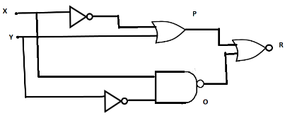
A system of logic gates is shown in the figure. From the study of truth table it can be found that no produce a high output (1) at R, we must have
A) X = 0, Y = 1
B) X = 1, Y = 1
C) X = 1, Y = 0
D) X = 0, Y = 0
Answer
605.7k+ views
Hint:Find the outputs from the individual gates and substitute in the truth table to finally get the output from the last gate R.Only 0 and 1 can be the inputs and higher value amongst them is 1.
Complete step by step answer:
We can input only binary numbers (0 and 1) in the logic gates and the higher output is 1.
Different types of logic gates with their symbols are:
1. AND Gate

The output will be one only if both the inputs are 1 and in this gate product of the inputs is considered.
2. OR Gate
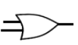
The output is one when either of the inputs is 1.Sum of the inputs is considered on this type of gate.
3. NOT Gate
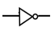
The output is just the opposite of the input.Only the circle can also represent the Not gate and the sign of a bar is used to denote it.
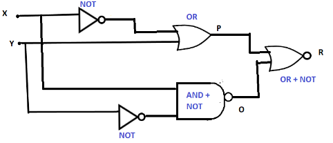
Now, using these we can make a truth table for the given diagram by naming the gates:
The truth table can be drawn for possible binary numbers as:
It can be seen that one achieves higher value i.e. 1 only at one condition and that condition in X and Y is:
X = 1
Y = 0
Thus, the correct option is C).
Note: All these 3 gates (AND, OR and NOT) are called basic logic gates and more logic gates can be derived from these.Be careful while observing the inputs on different gates from different gates, especially if NOT gate is connected or not. Follow the input lines carefully and move ahead from one to another in a proper order to avoid the confusion and intermixing.
Complete step by step answer:
We can input only binary numbers (0 and 1) in the logic gates and the higher output is 1.
Different types of logic gates with their symbols are:
1. AND Gate
The output will be one only if both the inputs are 1 and in this gate product of the inputs is considered.
2. OR Gate
The output is one when either of the inputs is 1.Sum of the inputs is considered on this type of gate.
3. NOT Gate
The output is just the opposite of the input.Only the circle can also represent the Not gate and the sign of a bar is used to denote it.
Now, using these we can make a truth table for the given diagram by naming the gates:
The truth table can be drawn for possible binary numbers as:
| X | Y | $\overline X $ | $\overline Y $ | $P = \overline X + Y$ | $O = \overline {X\overline Y } $ | $ R = \overline {P + Q} \\ R = \overline {\overline X + Y} \\ $ |
| 0 | 1 | 1 | 0 | 1 | 1 | 0 |
| 1 | 1 | 0 | 0 | 1 | 1 | 0 |
| 1 | 0 | 0 | 1 | 0 | 0 | 1 |
| 0 | 0 | 1 | 1 | 1 | 1 | 0 |
It can be seen that one achieves higher value i.e. 1 only at one condition and that condition in X and Y is:
X = 1
Y = 0
Thus, the correct option is C).
Note: All these 3 gates (AND, OR and NOT) are called basic logic gates and more logic gates can be derived from these.Be careful while observing the inputs on different gates from different gates, especially if NOT gate is connected or not. Follow the input lines carefully and move ahead from one to another in a proper order to avoid the confusion and intermixing.
Recently Updated Pages
Master Class 12 Business Studies: Engaging Questions & Answers for Success
Master Class 12 Biology: Engaging Questions & Answers for Success
Master Class 12 Chemistry: Engaging Questions & Answers for Success
Class 12 Question and Answer - Your Ultimate Solutions Guide
Master Class 11 Social Science: Engaging Questions & Answers for Success
Master Class 11 English: Engaging Questions & Answers for Success
Trending doubts
Which is more stable and why class 12 chemistry CBSE
Which are the Top 10 Largest Countries of the World?
Draw a labelled sketch of the human eye class 12 physics CBSE
Differentiate between homogeneous and heterogeneous class 12 chemistry CBSE
What are the major means of transport Explain each class 12 social science CBSE
Sulphuric acid is known as the king of acids State class 12 chemistry CBSE