


A resistor of $500\Omega$, and inductance of $0.5H$ are in series with an AC which is given by $V = 100\sqrt{2}sin(1000t)$. The power factor of the combination is:
A.$\dfrac{1}{\sqrt{2}}$
B.$\dfrac{1}{\sqrt{3}}$
C.$0.5$
D.$0.6$
Answer
628.8k+ views
Hint: Recall that the power factor is the ratio of the resistive power (resistance) to the reactive power (resultant of resistance and inductive reactance) taken as a cosine. Remember that the inductance changes sinusoidally with time just like AC. So, account for the angular frequency of these sinusoidal oscillations (which you can obtain from the alternating voltage) while calculating the inductive reactance. With this as guidance, plug in the values given in the question, and you should be able to arrive at the appropriate power factor.
Formula Used:
Power factor for an L-R circuit $cos\phi = \dfrac{R}{\sqrt{R^2+X_L^2}}$
Complete answer:
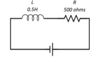
We have a circuit consisting of an inductor of $0.5H$, a resistor of $500\Omega$ and an AC supply voltage given by $V = 100\sqrt{2}sin(1000t)$ as shown in the circuit diagram.
We have an AC voltage source supplying a sinusoidal current. The general form of such a current is given by $V=V_0 sin(\omega t)$ where $V_0$ is the peak voltage, $\omega$ is the angular frequency of oscillations and t is an instant of time. Therefore, from the expression we have:
$V_0 = 100\sqrt{2},\; \omega = 1000$
Now, the impedance to the flow of current through the circuit is offered by both the resistor and the inductor.
The resistance offered to the flow of AC by the resistor is called resistance.
It is given as $R = 500\Omega$
The resistance offered to the flow of AC by the inductor is called as inductive reactance.This is given as $X_L = \omega L$, where $\omega$ is the angular frequency of AC and L is the value of inductance. For our circuit, we have
$X_L = 1000 \times 0.5 = 500\Omega$ and has the dimensions of resistance.
Now, the phasor diagram for the L-R circuit is shown below.
We know that an inductor stores electrical energy whereas a resistor dissipates electrical energy. The power factor for this L-R circuit is defined as the ratio of true power (resistive power) to apparent power (reactive power). This is given in the phase diagram as the cosine of the phase difference between the resistance and the inductive reactance.
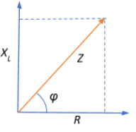
Z is the net impedance offered to the AC flow by all the components of the circuit. This is given as the resultant of resistance and inductive reactance.
Therefore, power factor $cos\phi = \dfrac{R}{Z} = \dfrac{R}{\sqrt{R^2+X_L^2}} = \dfrac{500}{\sqrt{500^2 + 500^2}}$
$\Rightarrow cos\phi = \dfrac{500}{\sqrt{500000}} = \dfrac{500}{\sqrt{250000 \times 2}} = \dfrac{500}{\sqrt{500^2 \times 2}} = \dfrac{500}{500\sqrt{2}}$
$\Rightarrow cos\phi=\dfrac{1}{\sqrt{2}}$
Therefore, the correct choice would be A. $\dfrac{1}{\sqrt{2}}$.
Note:
Remember that for all nonzero values of inductance (L), the power factor of an L-R circuit remains lagging, since the inductive reactance varies sinusoidally with AC while the resistance does not. This also means that the alternating current lags behind the voltage. In both cases, this lagging is by a factor of $\phi$ which is called the phase difference.
In the context of our question, we got $cos\phi=\dfrac{1}{\sqrt{2}} \Rightarrow \phi = 45^{\circ}$.
This means that the current lags behind voltage by a factor of $\phi = 45^{\circ}$
Formula Used:
Power factor for an L-R circuit $cos\phi = \dfrac{R}{\sqrt{R^2+X_L^2}}$
Complete answer:
We have a circuit consisting of an inductor of $0.5H$, a resistor of $500\Omega$ and an AC supply voltage given by $V = 100\sqrt{2}sin(1000t)$ as shown in the circuit diagram.
We have an AC voltage source supplying a sinusoidal current. The general form of such a current is given by $V=V_0 sin(\omega t)$ where $V_0$ is the peak voltage, $\omega$ is the angular frequency of oscillations and t is an instant of time. Therefore, from the expression we have:
$V_0 = 100\sqrt{2},\; \omega = 1000$
Now, the impedance to the flow of current through the circuit is offered by both the resistor and the inductor.
The resistance offered to the flow of AC by the resistor is called resistance.
It is given as $R = 500\Omega$
The resistance offered to the flow of AC by the inductor is called as inductive reactance.This is given as $X_L = \omega L$, where $\omega$ is the angular frequency of AC and L is the value of inductance. For our circuit, we have
$X_L = 1000 \times 0.5 = 500\Omega$ and has the dimensions of resistance.
Now, the phasor diagram for the L-R circuit is shown below.
We know that an inductor stores electrical energy whereas a resistor dissipates electrical energy. The power factor for this L-R circuit is defined as the ratio of true power (resistive power) to apparent power (reactive power). This is given in the phase diagram as the cosine of the phase difference between the resistance and the inductive reactance.
Z is the net impedance offered to the AC flow by all the components of the circuit. This is given as the resultant of resistance and inductive reactance.
Therefore, power factor $cos\phi = \dfrac{R}{Z} = \dfrac{R}{\sqrt{R^2+X_L^2}} = \dfrac{500}{\sqrt{500^2 + 500^2}}$
$\Rightarrow cos\phi = \dfrac{500}{\sqrt{500000}} = \dfrac{500}{\sqrt{250000 \times 2}} = \dfrac{500}{\sqrt{500^2 \times 2}} = \dfrac{500}{500\sqrt{2}}$
$\Rightarrow cos\phi=\dfrac{1}{\sqrt{2}}$
Therefore, the correct choice would be A. $\dfrac{1}{\sqrt{2}}$.
Note:
Remember that for all nonzero values of inductance (L), the power factor of an L-R circuit remains lagging, since the inductive reactance varies sinusoidally with AC while the resistance does not. This also means that the alternating current lags behind the voltage. In both cases, this lagging is by a factor of $\phi$ which is called the phase difference.
In the context of our question, we got $cos\phi=\dfrac{1}{\sqrt{2}} \Rightarrow \phi = 45^{\circ}$.
This means that the current lags behind voltage by a factor of $\phi = 45^{\circ}$
Recently Updated Pages
Master Class 12 Business Studies: Engaging Questions & Answers for Success
Master Class 12 Chemistry: Engaging Questions & Answers for Success
Master Class 12 Biology: Engaging Questions & Answers for Success
Class 12 Question and Answer - Your Ultimate Solutions Guide
Master Class 11 English: Engaging Questions & Answers for Success
Master Class 11 Social Science: Engaging Questions & Answers for Success
Trending doubts
Which are the Top 10 Largest Countries of the World?
Draw a labelled sketch of the human eye class 12 physics CBSE
Differentiate between homogeneous and heterogeneous class 12 chemistry CBSE
Differentiate between Pyramid of energy and pyramid class 12 biology CBSE
Why is the cell called the structural and functional class 12 biology CBSE
Draw the diagram of the pyramid of energy Explain In class 12 biology CBSE