


A coil has an inductance of 0.7H and is joined in series with a resistance of $220\Omega $ . When an alternating e.m.f of 220V at 50c.p.s is applied to it, then the watt less component of current in the circuit is
a) 5 ampere
b) 0.5 ampere
c) 0.7 ampere
d) 7 ampere
Answer
536.1k+ views
Hint: The word watt less means that there is no net dissipation of power in the circuit connected to an alternating emf. In case of the circuit components connected to an A.C. circuit, the potential drop across them as well as the current circuit are to be considered as vectors. Hence by determining the phase angle from the phasor diagram of the LR circuit, we can determine the component of wattles current.
Formula used:
$Z=\sqrt{{{R}^{2}}+{{\left( 2\pi fL \right)}^{2}}}$
$\cos \varphi =\dfrac{R}{Z}$
Complete answer:
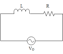
In the above diagram we can see that an inductor of inductance ‘L’ and a resistor of resistance ‘R’ is connected in series with an alternating emf ${{V}_{\circ }}$ with frequency ‘f’. let us say the resistance more precisely the inductive reactance ${{X}_{L}}$ of the inductor be $2\pi fL$ . Therefore we can imply the net impedance (Z) in the circuit is,
$Z=\sqrt{{{R}^{2}}+{{\left( 2\pi fL \right)}^{2}}}$
Since the resistance in the circuit R=$220\Omega $ inductance is 0.7H and frequency is 50 Hz, therefore the impedance in the circuit is,
$\begin{align}
& Z=\sqrt{{{R}^{2}}+{{\left( 2\pi fL \right)}^{2}}} \\
& \Rightarrow Z=\sqrt{{{220}^{2}}+{{\left( 2\pi \times 50\times 0.7 \right)}^{2}}} \\
& \Rightarrow Z=\sqrt{48400+48312.04} \\
& \Rightarrow Z=\sqrt{96712.04}\Omega \\
& \therefore Z=310.9\Omega \simeq 220\sqrt{2}\Omega \\
\end{align}$
Let us say them maximum current in the above circuit be ‘i’ Hence for a series LR circuit, the phasor diagram for the voltage across the resistor ${{V}_{R}}$ , the inductor ${{V}_{L}}$ and the net impedance ${{V}_{Z}}$ is shown in the diagram below.
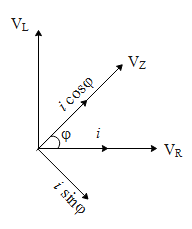
From the above phasor diagram the cos of the phase angle is,
$\begin{align}
& \cos \varphi =\dfrac{{{V}_{R}}}{{{V}_{Z}}} \\
& \because {{V}_{Z}}=iZ\text{, }{{V}_{R}}=iR \\
& \Rightarrow \cos \varphi =\dfrac{iR}{iZ} \\
& \therefore \cos \varphi =\dfrac{R}{Z} \\
\end{align}$
The above obtained component of the current in direction of the net impedance in the circuit i.e. (power factor), is responsible for the power consumption. The perpendicular component of current to this component i.e.$I=i\sin \phi $ does not get consumed and hence is known as wattles component of current.
The current in the circuit from the ohm's law is given by,
$\begin{align}
& i=\dfrac{{{V}_{Z}}}{Z} \\
& \Rightarrow i=\dfrac{220}{220\sqrt{2}}A \\
& \therefore \Rightarrow i=\dfrac{1}{\sqrt{2}}A \\
\end{align}$
Hence the wattless component of current in the circuit is,
$\begin{align}
& I=i\sin \phi \\
& \Rightarrow I=\dfrac{1}{\sqrt{2}}\sqrt{1-{{\cos }^{2}}\phi } \\
& \Rightarrow I=\dfrac{1}{\sqrt{2}}\sqrt{1-{{\left( \dfrac{1}{\sqrt{2}} \right)}^{2}}}=\dfrac{1}{\sqrt{2}}\sqrt{\dfrac{1}{2}} \\
& \therefore I=\dfrac{1}{2}A=0.5A \\
\end{align}$
Therefore the correct answer of the above question is option b.
Note:
The impedance basically means the net resistance in the circuit. Hence it has the unit of resistance. The frequency of the AC source is given as the number of cycles per second i.e, c.p.s, which is equal to the number of hertz. It is also to be noted that in an LR circuit, the current lags behind the voltage by the phase angle.
Formula used:
$Z=\sqrt{{{R}^{2}}+{{\left( 2\pi fL \right)}^{2}}}$
$\cos \varphi =\dfrac{R}{Z}$
Complete answer:
In the above diagram we can see that an inductor of inductance ‘L’ and a resistor of resistance ‘R’ is connected in series with an alternating emf ${{V}_{\circ }}$ with frequency ‘f’. let us say the resistance more precisely the inductive reactance ${{X}_{L}}$ of the inductor be $2\pi fL$ . Therefore we can imply the net impedance (Z) in the circuit is,
$Z=\sqrt{{{R}^{2}}+{{\left( 2\pi fL \right)}^{2}}}$
Since the resistance in the circuit R=$220\Omega $ inductance is 0.7H and frequency is 50 Hz, therefore the impedance in the circuit is,
$\begin{align}
& Z=\sqrt{{{R}^{2}}+{{\left( 2\pi fL \right)}^{2}}} \\
& \Rightarrow Z=\sqrt{{{220}^{2}}+{{\left( 2\pi \times 50\times 0.7 \right)}^{2}}} \\
& \Rightarrow Z=\sqrt{48400+48312.04} \\
& \Rightarrow Z=\sqrt{96712.04}\Omega \\
& \therefore Z=310.9\Omega \simeq 220\sqrt{2}\Omega \\
\end{align}$
Let us say them maximum current in the above circuit be ‘i’ Hence for a series LR circuit, the phasor diagram for the voltage across the resistor ${{V}_{R}}$ , the inductor ${{V}_{L}}$ and the net impedance ${{V}_{Z}}$ is shown in the diagram below.
From the above phasor diagram the cos of the phase angle is,
$\begin{align}
& \cos \varphi =\dfrac{{{V}_{R}}}{{{V}_{Z}}} \\
& \because {{V}_{Z}}=iZ\text{, }{{V}_{R}}=iR \\
& \Rightarrow \cos \varphi =\dfrac{iR}{iZ} \\
& \therefore \cos \varphi =\dfrac{R}{Z} \\
\end{align}$
The above obtained component of the current in direction of the net impedance in the circuit i.e. (power factor), is responsible for the power consumption. The perpendicular component of current to this component i.e.$I=i\sin \phi $ does not get consumed and hence is known as wattles component of current.
The current in the circuit from the ohm's law is given by,
$\begin{align}
& i=\dfrac{{{V}_{Z}}}{Z} \\
& \Rightarrow i=\dfrac{220}{220\sqrt{2}}A \\
& \therefore \Rightarrow i=\dfrac{1}{\sqrt{2}}A \\
\end{align}$
Hence the wattless component of current in the circuit is,
$\begin{align}
& I=i\sin \phi \\
& \Rightarrow I=\dfrac{1}{\sqrt{2}}\sqrt{1-{{\cos }^{2}}\phi } \\
& \Rightarrow I=\dfrac{1}{\sqrt{2}}\sqrt{1-{{\left( \dfrac{1}{\sqrt{2}} \right)}^{2}}}=\dfrac{1}{\sqrt{2}}\sqrt{\dfrac{1}{2}} \\
& \therefore I=\dfrac{1}{2}A=0.5A \\
\end{align}$
Therefore the correct answer of the above question is option b.
Note:
The impedance basically means the net resistance in the circuit. Hence it has the unit of resistance. The frequency of the AC source is given as the number of cycles per second i.e, c.p.s, which is equal to the number of hertz. It is also to be noted that in an LR circuit, the current lags behind the voltage by the phase angle.
Recently Updated Pages
Master Class 12 Economics: Engaging Questions & Answers for Success
Master Class 12 Physics: Engaging Questions & Answers for Success
Master Class 12 English: Engaging Questions & Answers for Success
Master Class 12 Social Science: Engaging Questions & Answers for Success
Master Class 12 Maths: Engaging Questions & Answers for Success
Master Class 12 Business Studies: Engaging Questions & Answers for Success
Trending doubts
Which are the Top 10 Largest Countries of the World?
What are the major means of transport Explain each class 12 social science CBSE
Draw a labelled sketch of the human eye class 12 physics CBSE
What is a transformer Explain the principle construction class 12 physics CBSE
Why cannot DNA pass through cell membranes class 12 biology CBSE
Differentiate between insitu conservation and exsitu class 12 biology CBSE