


Commutator: An Introduction
The use of DC devices for daily necessities has become a normal occurrence in our lives. DC generators and DC motors are two different types of DC machinery. DC generators turn mechanical motion into DC power, whereas DC motors turn DC electrical power into mechanical motion. The problem is that a DC generator produces AC current, even if its output is DC. Similar to how it applies when the power delivered to a DC motor is DC, the concept of the motor still holds true when the current in the coil alternates. So, how are these devices operating? The little gadget known as the "Commutator" is the solution to this puzzle.
What is a Commutator?
A group of bars or segments connected to the armature coils of the generator or motor to convert alternating current into direct current when the generator or motor turns.
Why is a Commutator Needed in Motors and Generators?
A motor's windings get an electric current from a commutator. By switching the direction of the current in the spinning windings every half turn, a constant rotational torque is generated. The commutator of a DC motor is made of copper.
A commutator in DC generator is used for the purpose of converting the alternating current from the generator's windings to unidirectional direct current in the external load circuit, the commutator inverts the direction of the current with each turn acting as a mechanical rectifier.
What is a Commutation?
In DC machines, the process of reversing current is known as commutation. The function served by the commutator of a DC generator is to convert the induced AC in conductors into a DC output. Before applying the DC current to the motor's coils, commutation is utilised in DC motors to switch the direction of the current.
Commutator Diagram
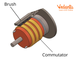
In This Diagram, Brushes are Connected with the Commutator
Working of Commutator
A commutator is a split rotary ring, usually made of copper, with one segment attached to each end of the armature coil. A commutator supporting each end of each coil on the multiple-coil armature must have the same number of segments. To provide the commutator segments and the accompanying armature coils with voltage, spring-loaded brushes are placed on each side of the commutator and make contact with it when the commutator rotates.
A constant rotating force known as torque is created by switching the direction of the current flowing through the revolving windings every half turn. With each half turn, the commutator in a generator reverses the direction of the current it picks up from the windings, acting as a mechanical rectifier to change the AC from the windings to unidirectional DC in the circuit.
Types of Commutation
When the current reversal is finished by the end of the commutation time, the calculation is known as an ideal commutation. If the current reversal is finished during the commutation time, sparking at the brush contact and overheating that damages the commutator surface take place.
There are three types of commutation methods to avoid defects.
Resistance Commutation
EMF Commutation
Compensating Winding
Interesting Facts
The armature of power tools, home appliances, starting motors, windscreen wipers, and the automobile sector all use commutators.
The commutator's segments are composed of copper and are spaced apart by mica insulation. The mica is shaped to sit beneath the copper strands. To make soldering the coil ends easier, slots are carved into the riser of the commutator.
Solved Questions
1. Why is the commutator made up of copper?
Solution: In brushed commutators, the brushes are typically constructed of either copper or. Carbon brushes have more uniform wear, produce less sparking, and harm the conductive metal segments less. However, copper brushes work better with high currents and extremely low voltage.
2. What would happen if the commutator was not there?
Solution: The magnetic fields of the rotor and stator would collide in the absence of a split ring commutator, preventing the current from reversing when the armature is reversed. As a result, the rotor would become stuck and cease to rotate.
Summary
A popular switch used in electronic products is the commutator. A torque, or constant rotating force, is created when the direction of the current flow changes every half revolution of the winding. The way the shaft, commutator, and armature are wound r determines how well the commutator functions. Although the voltage produced in the commutator might be zero to maximum, the polarity always remains fixed. A commutator has two main purposes: it maintains constant armature torque and MMF and transforms alternating current into direct current, serving as a rectifier in the process.
FAQs on Commutator
1. What is the main function of a commutator in an electric motor?
The main function of a commutator is to reverse the direction of the electric current in the armature coil of a DC motor after every half rotation. This reversal ensures that the torque on the coil always acts in the same direction, allowing the motor to rotate continuously. It essentially acts as a rotary switch.
2. What is a commutator made of?
A commutator is typically made of a segmented copper ring. Each segment is insulated from the others, usually with thin sheets of mica. Two carbon brushes press against the rotating commutator segments to supply current to the armature coil.
3. Where can we find commutators in everyday devices?
You can find commutators in many devices that use a DC motor. Common examples include:
- Electric toys like remote-controlled cars
- Household appliances like mixers and blenders
- Power tools like electric drills
- The starter motor in cars
4. What is the difference between a split-ring commutator and slip rings?
The key difference lies in their function and construction. A split-ring commutator is a single ring split into two or more parts, designed to reverse the current's direction. It is used in DC motors and DC generators. In contrast, slip rings are two complete, separate rings that maintain a continuous connection, allowing current to flow in and out without reversing. They are used in AC generators.
5. How does a commutator help a DC motor rotate continuously in one direction?
A commutator acts as a reversing switch. As the motor's coil rotates due to magnetic force, the commutator rotates with it. After exactly half a turn, the brushes cross the gap in the split ring and make contact with the opposite segment. This instantly flips the direction of the current in the coil. By doing this every half turn, the direction of the force on each arm of the coil is also reversed, ensuring the torque always pushes the coil in the same rotational direction.
6. What would happen if a DC motor did not have a commutator?
Without a commutator, a simple DC motor would not work properly. The coil would rotate for the first half turn until it reaches the vertical position. At that point, the direction of the torque would reverse, pushing the coil back to its starting position. The motor would just oscillate back and forth around the vertical position instead of completing a full, continuous rotation.
7. Why isn't a commutator used in an AC generator?
A commutator's job is to turn AC into DC. In a DC generator, alternating current is naturally induced in the coil, and the commutator rectifies it to produce a direct current output. An AC generator, however, is designed to produce alternating current, so it uses slip rings instead. Slip rings maintain the AC output without converting it.
8. Are split rings and commutators the same thing?
Yes, in the context of a simple DC motor as studied in the CBSE syllabus, the term 'split ring' is often used interchangeably with 'commutator'. The split ring is the device that performs the action of commutation (reversing the current). So, when you see 'split-ring commutator,' it refers to this specific component.