


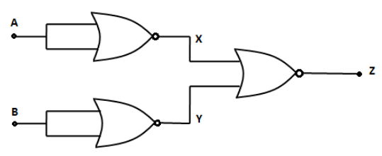
You are given a circuit below. Write its truth table. Hence, identify the logic operation carried out by this circuit. Draw the logic symbol of the gate it represents to.
Answer
561.6k+ views
Hint: In the above logic diagram, the output of the two NOR gates is given to the input of the third NOR gate. Since there is only one input to the first two NOR gates, their output will be the negation of the input. The output of NOR gate is high only when the both inputs are low.
Complete answer:
We have given that the output of the two NOR gates is given to the input of the third NOR gate. Since there is only one input to the first two NOR gates, their output will be the negation of the input.We know that the output of NOR gate is high only when the both inputs are low. Let us draw the truth table of the above logic circuit as below.
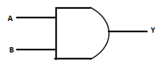
In the above truth table, we can see that the output Z is 1 only when both the inputs A and B are 1. We know that this is the case of AND gate. We have the output of AND gate,
Therefore, the logic operation carried out by the above logic diagram is multiplication. We have the symbol of AND gate,
Note: Students must note that if there is a dot after the AND gate, this means that the output is negation of the AND gate. This gate is known as NAND gate. The addition of the inputs in the OR gate for input 1 and 1 is always 1.
Complete answer:
We have given that the output of the two NOR gates is given to the input of the third NOR gate. Since there is only one input to the first two NOR gates, their output will be the negation of the input.We know that the output of NOR gate is high only when the both inputs are low. Let us draw the truth table of the above logic circuit as below.
| A | B | X | Y | \[Z = \overline {X + Y} \] |
| 0 | 0 | 1 | 1 | 0 |
| 0 | 1 | 1 | 0 | 0 |
| 1 | 0 | 0 | 1 | 0 |
| 1 | 1 | 0 | 0 | 1 |
In the above truth table, we can see that the output Z is 1 only when both the inputs A and B are 1. We know that this is the case of AND gate. We have the output of AND gate,
| A | B | \[Y = A \cdot B\] |
| 0 | 0 | 0 |
| 0 | 1 | 0 |
| 1 | 0 | 0 |
| 1 | 1 | 1 |
Therefore, the logic operation carried out by the above logic diagram is multiplication. We have the symbol of AND gate,
Note: Students must note that if there is a dot after the AND gate, this means that the output is negation of the AND gate. This gate is known as NAND gate. The addition of the inputs in the OR gate for input 1 and 1 is always 1.
Recently Updated Pages
Master Class 12 Economics: Engaging Questions & Answers for Success
Master Class 12 Physics: Engaging Questions & Answers for Success
Master Class 12 English: Engaging Questions & Answers for Success
Master Class 12 Social Science: Engaging Questions & Answers for Success
Master Class 12 Maths: Engaging Questions & Answers for Success
Master Class 12 Business Studies: Engaging Questions & Answers for Success
Trending doubts
Which are the Top 10 Largest Countries of the World?
What are the major means of transport Explain each class 12 social science CBSE
Draw a labelled sketch of the human eye class 12 physics CBSE
Why cannot DNA pass through cell membranes class 12 biology CBSE
Differentiate between insitu conservation and exsitu class 12 biology CBSE
Draw a neat and well labeled diagram of TS of ovary class 12 biology CBSE