


With the functional block diagram explain the working of a monochrome TV transmitter.
Answer
622.8k+ views
Hint: Monochrome TV transmitter consists of a television camera, video amplifier, AM modulating amplifier, audio amplifier, FM modulating amplifier, FM sound transmitter, crystal oscillator, RF amplifier, power amplifier, Scanning and synchronizing circuits, Transmitter antenna, microphone and Combining network.
Complete step by step answer:
Television is formed by combining two words: tele and vision. It means to see the picture which are telecasted from a long distance. It is a telecommunication medium used for transmitting images and sound. These images can be monochrome i.e. black and white or color.
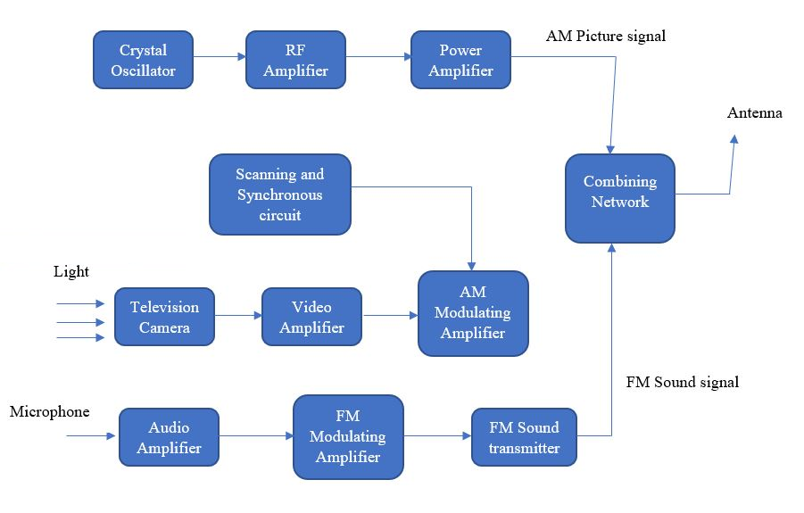
The above figure shows the functional block diagram of a monochrome TV transmitter. It consists of a television camera, video amplifier, AM modulating amplifier, audio amplifier, FM modulating amplifier, FM sound transmitter, crystal oscillator, RF amplifier, power amplifier, Scanning and synchronizing circuits, Transmitter antenna, microphone and Combining network.
In TV transmission, both sound and picture are transmitted. AM Modulators are used for picture while FM Modulators are used for sound.
In Monochrome Tv transmission, scanning and synchronizing circuits produce sets of pulses for providing pulses for proper functioning of TV systems. Scanning and Synchronizing circuits includes wave generating and shaping circuits. Examples of these circuits are Multivibrator circuits, clipping circuits etc.
The output signal of a camera tube corresponding to the image to be screened on the television is amplified through the video amplifier stage. The image signals together with the synchronizing pulses are raised to a level for modulating RF carrier waves generated in the RF channel. The crystal oscillators are used to generate allotted picture frequency. Then the wave output is amplified and then fed to the power amplifier.
The microphone converts the sound related to the image being screened into proportional electrical signal. Then the audio signal from the microphone is amplified. After amplification, the audio signal is frequency modulated.
The outputs from picture signal transmitter and sound signal transmitter are combined through a combining network and then fed to a common transmitter antenna for transmission.
Note: The signals received by Transmitter antennas are in the form of electromagnetic waves. Working of monochrome TV transmitters and color TV transmitters are quite different. Similarly working of receivers is also different from that of transmitters. So try to understand their working rather than memorizing them.
Complete step by step answer:
Television is formed by combining two words: tele and vision. It means to see the picture which are telecasted from a long distance. It is a telecommunication medium used for transmitting images and sound. These images can be monochrome i.e. black and white or color.
The above figure shows the functional block diagram of a monochrome TV transmitter. It consists of a television camera, video amplifier, AM modulating amplifier, audio amplifier, FM modulating amplifier, FM sound transmitter, crystal oscillator, RF amplifier, power amplifier, Scanning and synchronizing circuits, Transmitter antenna, microphone and Combining network.
In TV transmission, both sound and picture are transmitted. AM Modulators are used for picture while FM Modulators are used for sound.
In Monochrome Tv transmission, scanning and synchronizing circuits produce sets of pulses for providing pulses for proper functioning of TV systems. Scanning and Synchronizing circuits includes wave generating and shaping circuits. Examples of these circuits are Multivibrator circuits, clipping circuits etc.
The output signal of a camera tube corresponding to the image to be screened on the television is amplified through the video amplifier stage. The image signals together with the synchronizing pulses are raised to a level for modulating RF carrier waves generated in the RF channel. The crystal oscillators are used to generate allotted picture frequency. Then the wave output is amplified and then fed to the power amplifier.
The microphone converts the sound related to the image being screened into proportional electrical signal. Then the audio signal from the microphone is amplified. After amplification, the audio signal is frequency modulated.
The outputs from picture signal transmitter and sound signal transmitter are combined through a combining network and then fed to a common transmitter antenna for transmission.
Note: The signals received by Transmitter antennas are in the form of electromagnetic waves. Working of monochrome TV transmitters and color TV transmitters are quite different. Similarly working of receivers is also different from that of transmitters. So try to understand their working rather than memorizing them.
Recently Updated Pages
Master Class 12 Business Studies: Engaging Questions & Answers for Success
Master Class 12 Chemistry: Engaging Questions & Answers for Success
Master Class 12 Biology: Engaging Questions & Answers for Success
Class 12 Question and Answer - Your Ultimate Solutions Guide
Master Class 11 English: Engaging Questions & Answers for Success
Master Class 11 Social Science: Engaging Questions & Answers for Success
Trending doubts
Which are the Top 10 Largest Countries of the World?
Draw a labelled sketch of the human eye class 12 physics CBSE
The end of compass needle which points towards north class 12 physics CBSE
Differentiate between homogeneous and heterogeneous class 12 chemistry CBSE
In order to find out the different types of gametes class 12 biology NEET_UG
Why is the cell called the structural and functional class 12 biology CBSE