


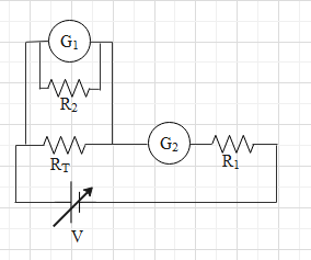
To verify Ohm’s law, a student is provided with a test resistor ${{R}_{T}}$, a high resistance ${{R}_{1}}$, a small resistance ${{R}_{2}}$, two identical galvanometers ${{G}_{1}}$ and ${{G}_{2}}$, and a variable voltage source V. The correct circuit to carry out the experiment is
A.
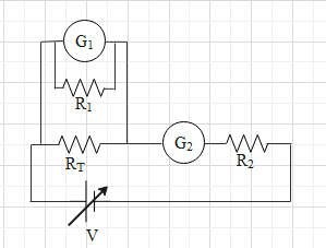
B.
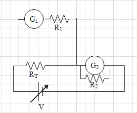
C.
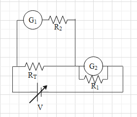
D.
Answer
597.3k+ views
Hint: An ammeter is made by connecting a high resistance (${{R}_{1}}$) in parallel to a galvanometer. A voltmeter is made by attaching a low resistance (${{R}_{2}}$) in series with a galvanometer. An ammeter is always connecting series and a voltmeter is always connected in parallel.
Complete step-by-step answer:
Let us first under Ohm’s law. According to Ohm’s law, the current in a resistor is directly proportional to the potential difference across the resistor.
To verify the Ohm’s law one needs a test resistor, a variable voltage source to create a potential difference across the test resistor, an ammeter and a voltmeter.
An ammeter is used to measure the current in the circuit and its always connected in series with the resistor (or other components).
An voltmeter is used to measure the potential difference across the resistor. It is connected in parallel with resistor.
To verify Ohm’s law, the student has to change the voltage of the source and observe the relation between the change in potential difference across the test resistor and change in the current in it.
However, the student is provided with two galvanometers and one high resistance and one low resistance, instead of an ammeter and a voltmeter.
But, we can make an ammeter and a voltage with the galvanometers and the resistances.
An ammeter is made by connecting a high resistance (${{R}_{1}}$) in parallel to a galvanometer.
A voltmeter is made by attaching a low resistance (${{R}_{2}}$) in series with a galvanometer.
In correct D, the combination of ${{R}_{2}}$ and ${{G}_{1}}$ acts as a voltmeter and it is connected in parallel with ${{R}_{T}}$. The combination of ${{R}_{1}}$ and ${{G}_{2}}$ acts as an ammeter and it is connected in series with ${{R}_{T}}$.
Therefore, the correct circuit is D.
So, the correct answer is “Option D”.
Note: In voltmeter a low resistance is connected in series with the galvanometer because the job of the voltmeter is to measure the potential difference across the resistor without taking in any current. Due to a small resistance, a very little current will flow through the voltmeter. This way it does not interrupt with the circuit.
By connecting a high resistance in parallel with the galvanometer, the resistance of the ammeter becomes very low. Due to low resistance, it does not alter the current in the circuit.
Recently Updated Pages
Master Class 12 Business Studies: Engaging Questions & Answers for Success
Master Class 12 Biology: Engaging Questions & Answers for Success
Master Class 12 Chemistry: Engaging Questions & Answers for Success
Class 12 Question and Answer - Your Ultimate Solutions Guide
Master Class 11 Social Science: Engaging Questions & Answers for Success
Master Class 11 English: Engaging Questions & Answers for Success
Trending doubts
Which is more stable and why class 12 chemistry CBSE
Which are the Top 10 Largest Countries of the World?
Draw a labelled sketch of the human eye class 12 physics CBSE
Differentiate between homogeneous and heterogeneous class 12 chemistry CBSE
What are the major means of transport Explain each class 12 social science CBSE
Sulphuric acid is known as the king of acids State class 12 chemistry CBSE