


The values of${{X}_{L}}$ , ${{X}_{C}}$ and R in series with an A.C. circuit are$8\Omega $ , $6\Omega $ and $10\Omega $ respectively. The total impedance of the circuit will be _________$\Omega $
A. 10.2
B. 12.2
C. 10
D. 24.4
Answer
586.2k+ views
Hint: Recall the phasor diagram of a LCR circuit, using Pythagorean theorem, you could express the amplitude of voltage across the source in terms of that across resistor, inductor and capacitor which could be further expressed in terms of current and resistance offered by each element. From there, you could derive the expression for impedance which is nothing but the resultant opposition offered by all the elements.
Formula used: Expression for impedance,
$Z=\sqrt{{{R}^{2}}+{{\left( {{X}_{C}}-{{X}_{L}} \right)}^{2}}}$
Complete step by step answer:
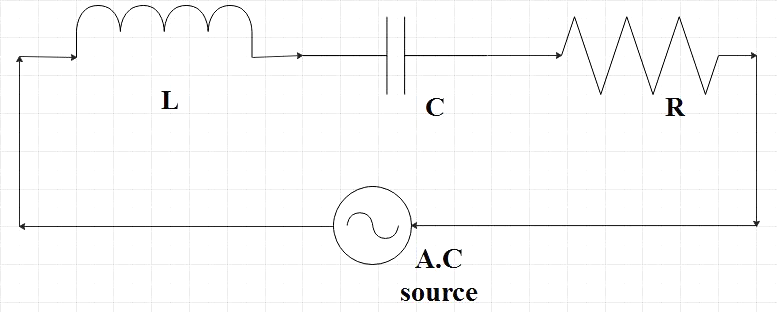
We are given a series LCR circuit, that is, in the given circuit, an inductor, a capacitor and a resistor is connected in series with an AC voltage supply.
Let the voltage of the given voltage source be given by,
$v={{v}_{0}}\sin \omega t$
By Kirchoff’s voltage/loop rule, the algebraic sum of changes in potential around any closed loop is zero.
Voltage difference across an inductor,
${{V}_{L}}=L\dfrac{di}{dt}$
Voltage difference across a capacitor,
${{V}_{C}}=\dfrac{q}{C}$
Voltage difference across a resistor,
${{V}_{R}}=iR$
Now by Kirchoff’s loop rule,
${{V}_{L}}+{{V}_{C}}+{{V}_{R}}=v$
$L\dfrac{di}{dt}+\dfrac{q}{C}+iR=v$
Since the circuit is a series circuit with all the elements connected in series, the ac current in each of these elements is the same at any time.
$i={{i}_{0}}\sin \left( \omega t+\phi \right)$
Where, $\phi $ is the phase difference between voltage across the source and the current.
Let us look at the phasor-diagram with the current (i), voltages across the inductor, capacitor and resistor (${{V}_{L}}$ ,${{V}_{C}}$ and${{V}_{R}}$).Recall that, ${{V}_{R}}$ lies parallel to i but ${{V}_{c}}$ is $\dfrac{\pi }{2}$ behind and ${{V}_{L}}$ is $\dfrac{\pi }{2}$ ahead of i.
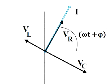
Which can be represented otherwise as,
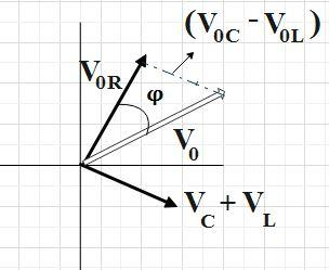
Here, ${{V}_{0}}$ forms the hypotenuse of a right triangle whose sides are ${{V}_{0R}}$ and$\left( {{V}_{0C}}-{{V}_{0L}} \right)$. So, by Pythagorean theorem, we have,
${{V}_{0}}^{2}={{V}_{0R}}^{2}+{{\left( {{V}_{0C}}-{{V}_{0L}} \right)}^{2}}$ ……………….. (1)
But we have,
${{V}_{0R}}={{i}_{0}}R$
${{V}_{0C}}={{i}_{0}}{{X}_{C}}$
${{V}_{0L}}={{i}_{0}}{{X}_{L}}$
Where, ${{X}_{C}}$ and ${{X}_{L}}$ are capacitive reactance and inductive reactance respectively. Reactance is nothing but the opposition offered by the given element to the flow of current.
Equation (1) can be written as,
${{V}_{0}}^{2}={{\left( {{i}_{0}}R \right)}^{2}}+{{\left( {{i}_{0}}{{X}_{c}}-{{i}_{0}}{{X}_{L}} \right)}^{2}}$
${{V}_{0}}^{2}={{i}_{0}}^{2}\left( {{R}^{2}}+{{\left( {{X}_{c}}-{{X}_{L}} \right)}^{2}} \right)$
Therefore,
${{i}_{0}}=\dfrac{{{V}_{0}}}{\sqrt{{{R}^{2}}+{{\left( {{X}_{C}}-{{X}_{L}} \right)}^{2}}}}$ …………………. (2)
Here, let us introduce a term called impedance. impedance is analogous to the resistance in a circuit but it also accounts for opposition offered by the capacitors and inductors.
Equation (2) now becomes,
${{i}_{0}}=\dfrac{{{V}_{0}}}{Z}$
Where, impedance Z is given by,
$Z=\sqrt{{{R}^{2}}+{{\left( {{X}_{C}}-{{X}_{L}} \right)}^{2}}}$ …………………. (3)
Now we could substitute the given values directly in the equation (3) to find the impedance.
${{X}_{L}}=8\Omega $
${{X}_{C}}=6\Omega $
$R=10\Omega $
$Z=\sqrt{{{\left( 10 \right)}^{2}}+{{\left( 6-8 \right)}^{2}}}$
$Z=\sqrt{100+4}=\sqrt{104}=10.2\Omega $
So, the correct answer is “Option A”.
Note: This lengthy derivation is done for your better understanding. You could avoid this lengthy derivation if you knew the expression for impedance directly. Or else, you could simply start the deriving from the phasor diagram of the LCR circuit using Pythagorean theorem.
Formula used: Expression for impedance,
$Z=\sqrt{{{R}^{2}}+{{\left( {{X}_{C}}-{{X}_{L}} \right)}^{2}}}$
Complete step by step answer:
We are given a series LCR circuit, that is, in the given circuit, an inductor, a capacitor and a resistor is connected in series with an AC voltage supply.
Let the voltage of the given voltage source be given by,
$v={{v}_{0}}\sin \omega t$
By Kirchoff’s voltage/loop rule, the algebraic sum of changes in potential around any closed loop is zero.
Voltage difference across an inductor,
${{V}_{L}}=L\dfrac{di}{dt}$
Voltage difference across a capacitor,
${{V}_{C}}=\dfrac{q}{C}$
Voltage difference across a resistor,
${{V}_{R}}=iR$
Now by Kirchoff’s loop rule,
${{V}_{L}}+{{V}_{C}}+{{V}_{R}}=v$
$L\dfrac{di}{dt}+\dfrac{q}{C}+iR=v$
Since the circuit is a series circuit with all the elements connected in series, the ac current in each of these elements is the same at any time.
$i={{i}_{0}}\sin \left( \omega t+\phi \right)$
Where, $\phi $ is the phase difference between voltage across the source and the current.
Let us look at the phasor-diagram with the current (i), voltages across the inductor, capacitor and resistor (${{V}_{L}}$ ,${{V}_{C}}$ and${{V}_{R}}$).Recall that, ${{V}_{R}}$ lies parallel to i but ${{V}_{c}}$ is $\dfrac{\pi }{2}$ behind and ${{V}_{L}}$ is $\dfrac{\pi }{2}$ ahead of i.
Which can be represented otherwise as,
Here, ${{V}_{0}}$ forms the hypotenuse of a right triangle whose sides are ${{V}_{0R}}$ and$\left( {{V}_{0C}}-{{V}_{0L}} \right)$. So, by Pythagorean theorem, we have,
${{V}_{0}}^{2}={{V}_{0R}}^{2}+{{\left( {{V}_{0C}}-{{V}_{0L}} \right)}^{2}}$ ……………….. (1)
But we have,
${{V}_{0R}}={{i}_{0}}R$
${{V}_{0C}}={{i}_{0}}{{X}_{C}}$
${{V}_{0L}}={{i}_{0}}{{X}_{L}}$
Where, ${{X}_{C}}$ and ${{X}_{L}}$ are capacitive reactance and inductive reactance respectively. Reactance is nothing but the opposition offered by the given element to the flow of current.
Equation (1) can be written as,
${{V}_{0}}^{2}={{\left( {{i}_{0}}R \right)}^{2}}+{{\left( {{i}_{0}}{{X}_{c}}-{{i}_{0}}{{X}_{L}} \right)}^{2}}$
${{V}_{0}}^{2}={{i}_{0}}^{2}\left( {{R}^{2}}+{{\left( {{X}_{c}}-{{X}_{L}} \right)}^{2}} \right)$
Therefore,
${{i}_{0}}=\dfrac{{{V}_{0}}}{\sqrt{{{R}^{2}}+{{\left( {{X}_{C}}-{{X}_{L}} \right)}^{2}}}}$ …………………. (2)
Here, let us introduce a term called impedance. impedance is analogous to the resistance in a circuit but it also accounts for opposition offered by the capacitors and inductors.
Equation (2) now becomes,
${{i}_{0}}=\dfrac{{{V}_{0}}}{Z}$
Where, impedance Z is given by,
$Z=\sqrt{{{R}^{2}}+{{\left( {{X}_{C}}-{{X}_{L}} \right)}^{2}}}$ …………………. (3)
Now we could substitute the given values directly in the equation (3) to find the impedance.
${{X}_{L}}=8\Omega $
${{X}_{C}}=6\Omega $
$R=10\Omega $
$Z=\sqrt{{{\left( 10 \right)}^{2}}+{{\left( 6-8 \right)}^{2}}}$
$Z=\sqrt{100+4}=\sqrt{104}=10.2\Omega $
So, the correct answer is “Option A”.
Note: This lengthy derivation is done for your better understanding. You could avoid this lengthy derivation if you knew the expression for impedance directly. Or else, you could simply start the deriving from the phasor diagram of the LCR circuit using Pythagorean theorem.
Recently Updated Pages
Master Class 12 Economics: Engaging Questions & Answers for Success
Master Class 12 Physics: Engaging Questions & Answers for Success
Master Class 12 English: Engaging Questions & Answers for Success
Master Class 12 Social Science: Engaging Questions & Answers for Success
Master Class 12 Maths: Engaging Questions & Answers for Success
Master Class 12 Business Studies: Engaging Questions & Answers for Success
Trending doubts
Which are the Top 10 Largest Countries of the World?
What are the major means of transport Explain each class 12 social science CBSE
Draw a labelled sketch of the human eye class 12 physics CBSE
Why cannot DNA pass through cell membranes class 12 biology CBSE
Differentiate between insitu conservation and exsitu class 12 biology CBSE
Draw a neat and well labeled diagram of TS of ovary class 12 biology CBSE