


The power factor of L – R circuit is:
A) $\dfrac{R}{{\omega L}}$
B) $\dfrac{R}{{{{\left( {\omega L} \right)}^2} + {R^2}}}$
C) $\omega LR$
D) $\sqrt {\omega LR} $
E) $\dfrac{R}{{\sqrt {{R^2} + {{\left( {\omega L} \right)}^2}} }}$
Answer
590.4k+ views
Hint: An L – R circuit consists of a resistor and an inductor connected in series with an alternating source of voltage. The power factor of such an L – R circuit is defined as the ratio of the resistance to the impedance offered by the circuit. The impedance of a circuit is the total resistance offered by all the components in the circuit to the flow of electrons.
Formulas used:
-The power factor of an L – R circuit is given by, $\cos \phi = \dfrac{R}{Z}$ where $R$ is the resistance of the resistor and $Z$ is the impedance offered by the circuit.
-The impedance of a series L – R circuit is given by, $Z = \sqrt {{R^2} + {X_L}^2} $ where $R$ is the resistance and ${X_L}$ is the inductive reactance.
Complete step by step solution:
Step 1: Sketch a circuit diagram of the given L – R circuit.
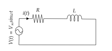
In the above L – R circuit, the resistor of resistance $R$ and the inductor of inductance $L$ are connected in series with the alternating voltage source.
The instantaneous voltage of the alternating source can be expressed as $V\left( t \right) = {V_m}\sin \omega t$ where ${V_m}$ is the peak value of the alternating voltage, $\omega $ is the angular frequency and $t$ is the time.
The instantaneous current through the circuit will be $i\left( t \right) = {i_m}\sin \left( {\omega t - \phi } \right)$ where ${i_m}$ is the peak value of the current, $\omega $ is the angular frequency, $t$ is the time and $\phi $ is the phase difference between the current and the voltage in the circuit.
The inductive reactance of the inductor in the above circuit is given by, ${X_L} = \omega L$ .
Step 2: Express the impedance offered by the L – R circuit.
The impedance offered by the above series L – R circuit can be expressed as
$Z = \sqrt {{R^2} + {X_L}^2} $ --------- (1)
Substituting for ${X_L} = \omega L$ in equation (1) we get the impedance offered by the circuit as $Z = \sqrt {{R^2} + {{\left( {\omega L} \right)}^2}} $ ---------- (2)
Step 3: Express the relation for the power factor of the L – R circuit.
The power factor of the given L – R circuit can be expressed as $\cos \phi = \dfrac{R}{Z}$ ------- (3)
Substituting equation (2) in (3) we get, $\cos \phi = \dfrac{R}{{\sqrt {{R^2} + {{\left( {\omega L} \right)}^2}} }}$
$\therefore $ the power factor is obtained to be $\cos \phi = \dfrac{R}{{\sqrt {{R^2} + {{\left( {\omega L} \right)}^2}} }}$ .
So the correct option is E.
Note: The power factor is actually the ratio of the actual power dissipation to the apparent power dissipation. If the circuit was purely resistive then the value of the power factor would be one whereas if it were a purely inductive circuit its value would be zero. In a series L – R circuit, the current lags behind the voltage. So the phase difference $\phi $ between the current and the voltage will be negative and the instantaneous current will be represented as $i\left( t \right) = {i_m}\sin \left( {\omega t - \phi } \right)$ . The current through the circuit has the same frequency as that of the applied voltage.
Formulas used:
-The power factor of an L – R circuit is given by, $\cos \phi = \dfrac{R}{Z}$ where $R$ is the resistance of the resistor and $Z$ is the impedance offered by the circuit.
-The impedance of a series L – R circuit is given by, $Z = \sqrt {{R^2} + {X_L}^2} $ where $R$ is the resistance and ${X_L}$ is the inductive reactance.
Complete step by step solution:
Step 1: Sketch a circuit diagram of the given L – R circuit.
In the above L – R circuit, the resistor of resistance $R$ and the inductor of inductance $L$ are connected in series with the alternating voltage source.
The instantaneous voltage of the alternating source can be expressed as $V\left( t \right) = {V_m}\sin \omega t$ where ${V_m}$ is the peak value of the alternating voltage, $\omega $ is the angular frequency and $t$ is the time.
The instantaneous current through the circuit will be $i\left( t \right) = {i_m}\sin \left( {\omega t - \phi } \right)$ where ${i_m}$ is the peak value of the current, $\omega $ is the angular frequency, $t$ is the time and $\phi $ is the phase difference between the current and the voltage in the circuit.
The inductive reactance of the inductor in the above circuit is given by, ${X_L} = \omega L$ .
Step 2: Express the impedance offered by the L – R circuit.
The impedance offered by the above series L – R circuit can be expressed as
$Z = \sqrt {{R^2} + {X_L}^2} $ --------- (1)
Substituting for ${X_L} = \omega L$ in equation (1) we get the impedance offered by the circuit as $Z = \sqrt {{R^2} + {{\left( {\omega L} \right)}^2}} $ ---------- (2)
Step 3: Express the relation for the power factor of the L – R circuit.
The power factor of the given L – R circuit can be expressed as $\cos \phi = \dfrac{R}{Z}$ ------- (3)
Substituting equation (2) in (3) we get, $\cos \phi = \dfrac{R}{{\sqrt {{R^2} + {{\left( {\omega L} \right)}^2}} }}$
$\therefore $ the power factor is obtained to be $\cos \phi = \dfrac{R}{{\sqrt {{R^2} + {{\left( {\omega L} \right)}^2}} }}$ .
So the correct option is E.
Note: The power factor is actually the ratio of the actual power dissipation to the apparent power dissipation. If the circuit was purely resistive then the value of the power factor would be one whereas if it were a purely inductive circuit its value would be zero. In a series L – R circuit, the current lags behind the voltage. So the phase difference $\phi $ between the current and the voltage will be negative and the instantaneous current will be represented as $i\left( t \right) = {i_m}\sin \left( {\omega t - \phi } \right)$ . The current through the circuit has the same frequency as that of the applied voltage.
Recently Updated Pages
Master Class 12 Social Science: Engaging Questions & Answers for Success
Master Class 12 Physics: Engaging Questions & Answers for Success
Master Class 12 Maths: Engaging Questions & Answers for Success
Master Class 12 Economics: Engaging Questions & Answers for Success
Master Class 12 Chemistry: Engaging Questions & Answers for Success
Master Class 12 Business Studies: Engaging Questions & Answers for Success
Trending doubts
Which are the Top 10 Largest Countries of the World?
Draw a labelled sketch of the human eye class 12 physics CBSE
Explain the structure of megasporangium class 12 biology CBSE
What are the major means of transport Explain each class 12 social science CBSE
How many chromosomes are found in human ovum a 46 b class 12 biology CBSE
The diagram of the section of a maize grain is given class 12 biology CBSE