


What will be the phase difference between input and output voltage of a common emitter circuit?
$\begin{align}
& A.0{}^\circ \\
& B.90{}^\circ \\
& C.180{}^\circ \\
& D.270{}^\circ \\
\end{align}$
Answer
571.5k+ views
Hint: The common emitter transistor circuit is defined as the one of the mainstay circuits used in the design of electronic circuits which is offering great advantages. The common emitter circuit configuration is having great use in various areas of electronic circuit design such as an audio amplifier, as a basic switch for logic circuits and so on.
Complete step by step solution:
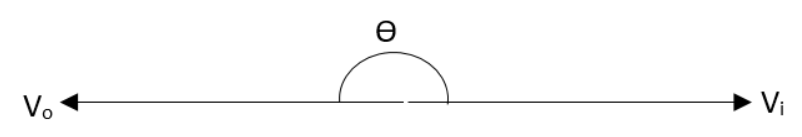
The common emitter transistor amplifier is only an electronic circuit which will provide an inversion of $180{}^\circ $between the input and output signals. The reason for this can be visualised from the fact that as the input voltage is increasing therefore the current also gets increased through the base circuit. Because of this, there will be an increase in the current through the collector circuit. That means it tends to turn the transistor on. This is the reason for the voltage between the collector and emitter terminals falling. In this manner an enhancement in the voltage between the base and emitter will be resulting in a fall in voltage between the collector and emitter terminals. In short we can say that the phase of the two signals has been inverted.
So, the correct answer is “Option C”.
Note: The common emitter circuit configuration is providing us with a voltage gain combined with a moderate current gain and also a medium output and a medium input impedance. The common emitter transistor amplifier which is inverting the signal at the input is also a primary use of this circuit. Therefore when a waveform that is rising which is entering the input of the common emitter amplifier. This will result in the output voltage to fall.
Complete step by step solution:
The common emitter transistor amplifier is only an electronic circuit which will provide an inversion of $180{}^\circ $between the input and output signals. The reason for this can be visualised from the fact that as the input voltage is increasing therefore the current also gets increased through the base circuit. Because of this, there will be an increase in the current through the collector circuit. That means it tends to turn the transistor on. This is the reason for the voltage between the collector and emitter terminals falling. In this manner an enhancement in the voltage between the base and emitter will be resulting in a fall in voltage between the collector and emitter terminals. In short we can say that the phase of the two signals has been inverted.
So, the correct answer is “Option C”.
Note: The common emitter circuit configuration is providing us with a voltage gain combined with a moderate current gain and also a medium output and a medium input impedance. The common emitter transistor amplifier which is inverting the signal at the input is also a primary use of this circuit. Therefore when a waveform that is rising which is entering the input of the common emitter amplifier. This will result in the output voltage to fall.
Recently Updated Pages
Master Class 12 Economics: Engaging Questions & Answers for Success
Master Class 12 Physics: Engaging Questions & Answers for Success
Master Class 12 English: Engaging Questions & Answers for Success
Master Class 12 Social Science: Engaging Questions & Answers for Success
Master Class 12 Maths: Engaging Questions & Answers for Success
Master Class 12 Business Studies: Engaging Questions & Answers for Success
Trending doubts
Why cannot DNA pass through cell membranes class 12 biology CBSE
Draw a neat and well labeled diagram of TS of ovary class 12 biology CBSE
In a human foetus the limbs and digits develop after class 12 biology CBSE
AABbCc genotype forms how many types of gametes a 4 class 12 biology CBSE
Differentiate between homogeneous and heterogeneous class 12 chemistry CBSE
The correct structure of ethylenediaminetetraacetic class 12 chemistry CBSE