


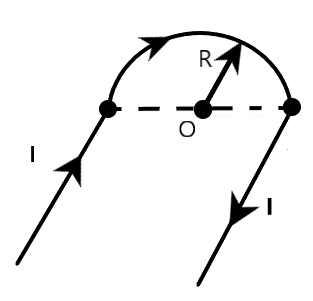
The magnetic induction at the point $O$, if the wire carrying current $I$ is:
$\begin{align}
& A)\dfrac{{{\mu }_{0}}I}{2R} \\
& B)\dfrac{{{\mu }_{0}}I}{2\pi R} \\
& C)\dfrac{{{\mu }_{0}}I{{({{\pi }^{2}}+4)}^{\dfrac{1}{2}}}}{4\pi R} \\
& D)\dfrac{{{\mu }_{0}}I({{\pi }^{2}}+4)}{4\pi R} \\
\end{align}$
Answer
579.6k+ views
Hint: The given figure is divided into three segments, which contain two straight current carrying wires and one semi-circular current carrying wire. The net magnetic field at point $O$ is the sum of magnetic induction at that point due to the two-current carrying straight wires and the magnetic induction at that point due to the semi-circular current carrying wire. A three-dimensional picture of the setup is visualized in order to solve the problem, easily.
Formula used:
$1)\overrightarrow{{{B}_{ST}}}=\dfrac{{{\mu }_{0}}I}{4\pi r}\widehat{n}$
$2)\overrightarrow{{{B}_{SC}}}=\dfrac{{{\mu }_{0}}I}{4r}\widehat{m}$
Complete step by step answer:
Firstly, let us study the given figure. We are provided with a wire, carrying a current $I$, arranged in a special pattern. We are required to find the magnetic field induction at point $O$, as shown in the figure. For this, let us visualize a three-dimensional picture of the setup. Let us also divide the wire into segments for easy calculations.
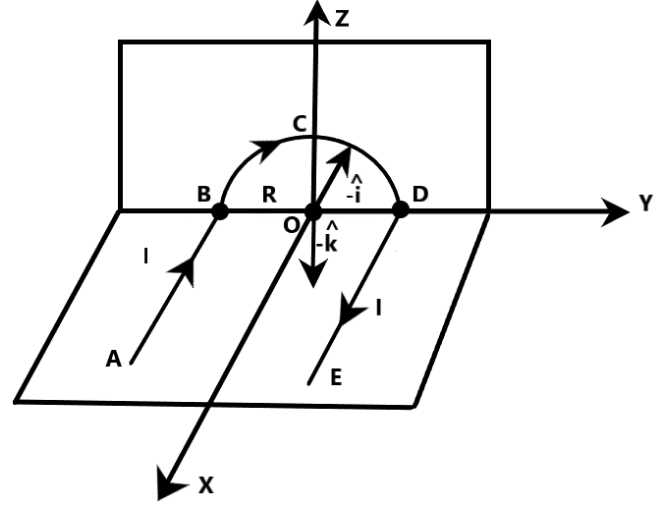
On clearly observing the figure given above, we can understand that the wire is divided into three segments. The first segment of wire is $AB$, which is nothing but a straight current carrying wire. The second segment of wire is denoted as $BCD$, which is nothing but a semi-circular current carrying wire, of radius $R$. The third segment of the wire is represented as $DE$, which is again a straight current carrying wire. Now, it is clear that all these three-current carrying segments will have an effect on the point $O$, due to magnetic induction. In order to determine the total magnetic field at this point, we have to add the magnetic fields generated at this point due to all the three segments, separately. If $\overrightarrow{B}$ is the total or the net magnetic field at point $O$, it is given by
$\overrightarrow{B}=\overrightarrow{{{B}_{AB}}}+\overrightarrow{{{B}_{BCD}}}+\overrightarrow{{{B}_{DE}}}$
where
$\overrightarrow{{{B}_{AB}}}$ is the magnetic field induction at point $O$, due to the straight segment $AB$
$\overrightarrow{{{B}_{BCD}}}$ is the magnetic field induction at point $O$, due to the semi-circular segment $BCD$
$\overrightarrow{{{B}_{DE}}}$ is the magnetic field induction at point $O$, due to the straight segment $DE$
Let this be equation 1.
Now, let us determine each one of these magnetic field inductions, separately.
From Biot-Savart law, we know that magnetic field induction due to a straight current carrying conductor at a point outside the conductor is given by
$\overrightarrow{{{B}_{ST}}}=\dfrac{{{\mu }_{0}}I}{4\pi r}\widehat{n}$
where
$\overrightarrow{{{B}_{ST}}}$ is the magnetic field induction due to a straight current-carrying conductor at a point outside the conductor
$I$ is the current flowing through the conductor
${{\mu }_{0}}$ is the permittivity of free space
$r$ is the perpendicular distance between the point and the conductor
$\widehat{n}$ is the direction of magnetic field at that point
Let this be equation 2.
From Biot-Savart law, we also know that magnetic field induction at the center of a semi-circular current carrying conductor is given by
$\overrightarrow{{{B}_{SC}}}=\dfrac{{{\mu }_{0}}I}{4r}\widehat{m}$
where
$\overrightarrow{{{B}_{SC}}}$ is the magnetic field induction at the center of a semi-circular current-carrying conductor
$I$ is the current flowing through the conductor
${{\mu }_{0}}$ is the permittivity of free space
$r$ is the radius of the semi-circular arc
$\widehat{m}$ is the direction of magnetic field at the center of the semi-circular segment
Let this be equation 3.
Now, we can use equation 1 to deduce the magnetic field inductions at point $O$, due to segments $AB$ as well $DE$ because both of these are straight current carrying conductors, with perpendicular distance from $O$, equal to the radius of the semi-circular arc, as given in the diagram.
Also, we can use equation 3 to deduce the magnetic field induction at point $O$, due to the semi-circular segment $BCD$, because point $O$ is the center of the semicircular arc, whose radius is given as $R$.
Therefore, using equation 2, we have
$\begin{align}
& \overrightarrow{{{B}_{AB}}}=\dfrac{{{\mu }_{0}}I}{4\pi R}(-\widehat{k}) \\
& \overrightarrow{{{B}_{DE}}}=\dfrac{{{\mu }_{0}}I}{4\pi R}(-\widehat{k}) \\
\end{align}$
where
$\overrightarrow{{{B}_{AB}}}$ is the magnetic field induction at point $O$, due to the straight segment $AB$ of the wire
$\overrightarrow{{{B}_{DE}}}$ is the magnetic field induction at point $O$, due to the straight segment $DE$ of the wire
$I$ is the current flowing through both these segments of wire
${{\mu }_{0}}$ is the permittivity of free space
$R$ is the perpendicular distance between the point and both these segments of wire
$(-\widehat{k})$ is the direction of magnetic field at point $O$, due to both these segments of wire
Let this set of equations be denoted by X.
Similarly, using equation 3, we have
$\overrightarrow{{{B}_{BCD}}}=\dfrac{{{\mu }_{0}}I}{4R}(-\widehat{i})$
where
$\overrightarrow{{{B}_{BCD}}}$ is the magnetic field induction at point $O$, due to the semi-circular segment $BCD$
$I$ is the current flowing through this segment of wire
${{\mu }_{0}}$ is the permittivity of free space
$R$ is the radius of semi-circular arc (segment) of the wire
$(-\widehat{i})$ is the direction of magnetic field at point $O$, due to segment $BCD$ of the wire
Let this be equation 4.
Substituting the set of equations in X and equation 4 in equation 1, we have
$\overrightarrow{B}=\overrightarrow{{{B}_{AB}}}+\overrightarrow{{{B}_{BCD}}}+\overrightarrow{{{B}_{DE}}}=\dfrac{{{\mu }_{0}}I}{4\pi R}(-\widehat{k})+\dfrac{{{\mu }_{0}}I}{4R}(-\widehat{i})+\dfrac{{{\mu }_{0}}I}{4\pi R}(-\widehat{k})=\dfrac{2{{\mu }_{0}}I}{4\pi R}(-\widehat{k})+\dfrac{{{\mu }_{0}}I}{4R}(-\widehat{i})$
where
$\overrightarrow{B}$ is the total or the net magnetic field at point $O$
Clearly, magnitude of net magnetic field at point $O$ is given by
$\left| \overrightarrow{B} \right|=\left| \dfrac{2{{\mu }_{0}}I}{4\pi R}(-\widehat{k})+\dfrac{{{\mu }_{0}}I}{4R}(-\widehat{i}) \right|=\dfrac{{{\mu }_{0}}I}{4\pi R}\sqrt{{{\pi }^{2}}+{{2}^{2}}}=\dfrac{{{\mu }_{0}}I}{4\pi R}\sqrt{{{\pi }^{2}}+4}$
Therefore, magnetic field induction at point $O$ due to the wire given in the figure is equal$\dfrac{{{\mu }_{0}}I}{4\pi R}\sqrt{{{\pi }^{2}}+4}$. Hence, the correct answer is option $C$.
Note:
Direction of the magnetic field due to the current carrying conductor is given by right hand thumb rule. In our solution, we have considered that the straight segments of the wire are in the $XY$ plane and the semi-circular segment of the wire is in the $ZY$ plane, as shown in the figure given above. Using right hand thumb rule, students can easily deduce that direction of magnetic field at $O$ due to both the segments $AB$ and $DE$ is in the negative z-direction $(-\widehat{k})$, as shown. Similarly, they can deduce that the direction of the magnetic field at point $O$, due to the segment $BCD$ is in the negative x-direction $(-\widehat{i})$, as shown. Since we are not asked to find the direction of the total magnetic field at point $O$ due to all the three segments, it is enough for us to calculate the magnitude of the net magnetic field, as done above.
Formula used:
$1)\overrightarrow{{{B}_{ST}}}=\dfrac{{{\mu }_{0}}I}{4\pi r}\widehat{n}$
$2)\overrightarrow{{{B}_{SC}}}=\dfrac{{{\mu }_{0}}I}{4r}\widehat{m}$
Complete step by step answer:
Firstly, let us study the given figure. We are provided with a wire, carrying a current $I$, arranged in a special pattern. We are required to find the magnetic field induction at point $O$, as shown in the figure. For this, let us visualize a three-dimensional picture of the setup. Let us also divide the wire into segments for easy calculations.
On clearly observing the figure given above, we can understand that the wire is divided into three segments. The first segment of wire is $AB$, which is nothing but a straight current carrying wire. The second segment of wire is denoted as $BCD$, which is nothing but a semi-circular current carrying wire, of radius $R$. The third segment of the wire is represented as $DE$, which is again a straight current carrying wire. Now, it is clear that all these three-current carrying segments will have an effect on the point $O$, due to magnetic induction. In order to determine the total magnetic field at this point, we have to add the magnetic fields generated at this point due to all the three segments, separately. If $\overrightarrow{B}$ is the total or the net magnetic field at point $O$, it is given by
$\overrightarrow{B}=\overrightarrow{{{B}_{AB}}}+\overrightarrow{{{B}_{BCD}}}+\overrightarrow{{{B}_{DE}}}$
where
$\overrightarrow{{{B}_{AB}}}$ is the magnetic field induction at point $O$, due to the straight segment $AB$
$\overrightarrow{{{B}_{BCD}}}$ is the magnetic field induction at point $O$, due to the semi-circular segment $BCD$
$\overrightarrow{{{B}_{DE}}}$ is the magnetic field induction at point $O$, due to the straight segment $DE$
Let this be equation 1.
Now, let us determine each one of these magnetic field inductions, separately.
From Biot-Savart law, we know that magnetic field induction due to a straight current carrying conductor at a point outside the conductor is given by
$\overrightarrow{{{B}_{ST}}}=\dfrac{{{\mu }_{0}}I}{4\pi r}\widehat{n}$
where
$\overrightarrow{{{B}_{ST}}}$ is the magnetic field induction due to a straight current-carrying conductor at a point outside the conductor
$I$ is the current flowing through the conductor
${{\mu }_{0}}$ is the permittivity of free space
$r$ is the perpendicular distance between the point and the conductor
$\widehat{n}$ is the direction of magnetic field at that point
Let this be equation 2.
From Biot-Savart law, we also know that magnetic field induction at the center of a semi-circular current carrying conductor is given by
$\overrightarrow{{{B}_{SC}}}=\dfrac{{{\mu }_{0}}I}{4r}\widehat{m}$
where
$\overrightarrow{{{B}_{SC}}}$ is the magnetic field induction at the center of a semi-circular current-carrying conductor
$I$ is the current flowing through the conductor
${{\mu }_{0}}$ is the permittivity of free space
$r$ is the radius of the semi-circular arc
$\widehat{m}$ is the direction of magnetic field at the center of the semi-circular segment
Let this be equation 3.
Now, we can use equation 1 to deduce the magnetic field inductions at point $O$, due to segments $AB$ as well $DE$ because both of these are straight current carrying conductors, with perpendicular distance from $O$, equal to the radius of the semi-circular arc, as given in the diagram.
Also, we can use equation 3 to deduce the magnetic field induction at point $O$, due to the semi-circular segment $BCD$, because point $O$ is the center of the semicircular arc, whose radius is given as $R$.
Therefore, using equation 2, we have
$\begin{align}
& \overrightarrow{{{B}_{AB}}}=\dfrac{{{\mu }_{0}}I}{4\pi R}(-\widehat{k}) \\
& \overrightarrow{{{B}_{DE}}}=\dfrac{{{\mu }_{0}}I}{4\pi R}(-\widehat{k}) \\
\end{align}$
where
$\overrightarrow{{{B}_{AB}}}$ is the magnetic field induction at point $O$, due to the straight segment $AB$ of the wire
$\overrightarrow{{{B}_{DE}}}$ is the magnetic field induction at point $O$, due to the straight segment $DE$ of the wire
$I$ is the current flowing through both these segments of wire
${{\mu }_{0}}$ is the permittivity of free space
$R$ is the perpendicular distance between the point and both these segments of wire
$(-\widehat{k})$ is the direction of magnetic field at point $O$, due to both these segments of wire
Let this set of equations be denoted by X.
Similarly, using equation 3, we have
$\overrightarrow{{{B}_{BCD}}}=\dfrac{{{\mu }_{0}}I}{4R}(-\widehat{i})$
where
$\overrightarrow{{{B}_{BCD}}}$ is the magnetic field induction at point $O$, due to the semi-circular segment $BCD$
$I$ is the current flowing through this segment of wire
${{\mu }_{0}}$ is the permittivity of free space
$R$ is the radius of semi-circular arc (segment) of the wire
$(-\widehat{i})$ is the direction of magnetic field at point $O$, due to segment $BCD$ of the wire
Let this be equation 4.
Substituting the set of equations in X and equation 4 in equation 1, we have
$\overrightarrow{B}=\overrightarrow{{{B}_{AB}}}+\overrightarrow{{{B}_{BCD}}}+\overrightarrow{{{B}_{DE}}}=\dfrac{{{\mu }_{0}}I}{4\pi R}(-\widehat{k})+\dfrac{{{\mu }_{0}}I}{4R}(-\widehat{i})+\dfrac{{{\mu }_{0}}I}{4\pi R}(-\widehat{k})=\dfrac{2{{\mu }_{0}}I}{4\pi R}(-\widehat{k})+\dfrac{{{\mu }_{0}}I}{4R}(-\widehat{i})$
where
$\overrightarrow{B}$ is the total or the net magnetic field at point $O$
Clearly, magnitude of net magnetic field at point $O$ is given by
$\left| \overrightarrow{B} \right|=\left| \dfrac{2{{\mu }_{0}}I}{4\pi R}(-\widehat{k})+\dfrac{{{\mu }_{0}}I}{4R}(-\widehat{i}) \right|=\dfrac{{{\mu }_{0}}I}{4\pi R}\sqrt{{{\pi }^{2}}+{{2}^{2}}}=\dfrac{{{\mu }_{0}}I}{4\pi R}\sqrt{{{\pi }^{2}}+4}$
Therefore, magnetic field induction at point $O$ due to the wire given in the figure is equal$\dfrac{{{\mu }_{0}}I}{4\pi R}\sqrt{{{\pi }^{2}}+4}$. Hence, the correct answer is option $C$.
Note:
Direction of the magnetic field due to the current carrying conductor is given by right hand thumb rule. In our solution, we have considered that the straight segments of the wire are in the $XY$ plane and the semi-circular segment of the wire is in the $ZY$ plane, as shown in the figure given above. Using right hand thumb rule, students can easily deduce that direction of magnetic field at $O$ due to both the segments $AB$ and $DE$ is in the negative z-direction $(-\widehat{k})$, as shown. Similarly, they can deduce that the direction of the magnetic field at point $O$, due to the segment $BCD$ is in the negative x-direction $(-\widehat{i})$, as shown. Since we are not asked to find the direction of the total magnetic field at point $O$ due to all the three segments, it is enough for us to calculate the magnitude of the net magnetic field, as done above.
Recently Updated Pages
Master Class 12 Economics: Engaging Questions & Answers for Success
Master Class 12 Physics: Engaging Questions & Answers for Success
Master Class 12 English: Engaging Questions & Answers for Success
Master Class 12 Social Science: Engaging Questions & Answers for Success
Master Class 12 Maths: Engaging Questions & Answers for Success
Master Class 12 Business Studies: Engaging Questions & Answers for Success
Trending doubts
Which are the Top 10 Largest Countries of the World?
What are the major means of transport Explain each class 12 social science CBSE
Draw a labelled sketch of the human eye class 12 physics CBSE
Why cannot DNA pass through cell membranes class 12 biology CBSE
Differentiate between insitu conservation and exsitu class 12 biology CBSE
Draw a neat and well labeled diagram of TS of ovary class 12 biology CBSE