


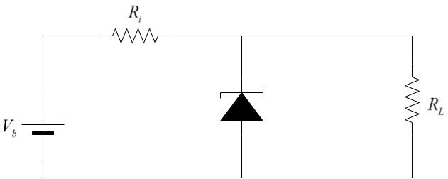
The figure represents a voltage regulator circuit using a Zener diode. The breakdown voltage of the Zener diode is 6V and load resistance is ${R_L} = 4k\Omega $ . The series resistance of the circuit is ${R_i} = 1k\Omega $. If the battery voltage ${V_B}$ varies from 8V to 16V, what are the minimum and maximum values of the current through Zener diode?
A. $0.5mA;6mA$
B. $0.5mA;8.5mA$
C. $1.5mA;8.5mA$
D. $1mA;8.5mA$
Answer
588.6k+ views
Hint: Zener diode is a special case which is constructed differently compared to a regular PN junction diode. The property of the Zener diode that makes it special, is its constant value of voltage across several ranges.
Complete Step by Step Answer:
The Zener diode is a special purpose semiconductor diode which is named after its creator, C. Zener. It is specifically designed to operate under reverse bias conditions. The Zener diode is created by heavily doping the n and p regions.
Due to the heavy doping, the depletion region formed in the Zener diode is very small. Thus, it can breakdown at very small voltages under reverse-bias.
Here, the Zener diode is operated in Reverse Bias only. When the voltage increases, there is less response of current up to the point where the voltage breakdown happens. At this point, the voltage drop across the Zener diode remains the same even though higher amounts of current can pass through it.
Here is the given circuit:

The bias voltage ${V_b}$ is connected in series with series resistor ${R_i}$ and the Zener diode. The load resistance has the same voltage drop as that of the Zener diode and is connected in parallel to the Zener diode as shown.
Zener breakdown voltage, ${V_z} = 6V$
If the input voltage is greater than the Zener breakdown voltage, the Zener diode allows only the breakdown voltage to flow through the load and the remaining excess voltage is dropped on the series resistance connected, so as to ensure that the voltage across the load does not exceed the breakdown voltage of the Zener diode.
Case 1: When ${V_b} = 8V$
Voltage drop across the series resistance, ${V_i} = 8 - 6 = 2V$
Given, ${R_i} = 1k\Omega $
Current flowing through series resistance, ${I_i} = \dfrac{{{V_i}}}{R}$
Substituting, we get –
${I_i} = \dfrac{2}{{{{10}^3}}} = 2 \times {10^{ - 3}}A = 2mA$
Since the voltage drop across the Zener diode and the load resistance is equal,
Current through load, ${I_L} = \dfrac{{{V_L}}}{{{R_L}}}$
Substituting, we get –
${I_L} = \dfrac{6}{{4 \times {{10}^3}}} = 1.5 \times {10^{ - 3}}A = 1.5mA$
Net current through Zener diode, ${I_z} = {I_i} - {I_L} = 2 - 1.5 = 0.5mA$
Case 2: When ${V_b} = 16V$
Voltage drop across the series resistance, ${V_i} = 16 - 6 = 10V$
Given, ${R_i} = 1k\Omega $
Current flowing through series resistance, ${I_i} = \dfrac{{{V_i}}}{R}$
Substituting, we get –
${I_i} = \dfrac{{10}}{{{{10}^3}}} = 10 \times {10^{ - 3}}A = 10mA$
Since the voltage drop across the Zener diode and the load resistance is equal,
Current through load, ${I_L} = \dfrac{{{V_L}}}{{{R_L}}}$
Substituting, we get –
${I_L} = \dfrac{6}{{4 \times {{10}^3}}} = 1.5 \times {10^{ - 3}}A = 1.5mA$
Net current through Zener diode, ${I_z} = {I_i} - {I_L} = 10 - 1.5 = 8.5mA$
Thus,
In case 1, when ${V_b} = 8V$, minimum current = $0.5mA$
In case 2, when ${V_b} = 16V$, maximum current = $8.5mA$
$\therefore$ The minimum current is $0.5mA$ and the maximum current is $8.5mA$. Hence, option (B) is the correct answer.
Note:
This property of Zener diodes is helpful in voltage regulation applications. Voltage regulators are used in stabiliser devices that are connected to sensitive appliances viz. television, fridge. Due to unexpected voltage surges due to lighting etc, the input voltage spikes and to protect the appliances from this surge voltage, the voltage regulator circuit is used in the stabiliser.
Complete Step by Step Answer:
The Zener diode is a special purpose semiconductor diode which is named after its creator, C. Zener. It is specifically designed to operate under reverse bias conditions. The Zener diode is created by heavily doping the n and p regions.
Due to the heavy doping, the depletion region formed in the Zener diode is very small. Thus, it can breakdown at very small voltages under reverse-bias.
Here, the Zener diode is operated in Reverse Bias only. When the voltage increases, there is less response of current up to the point where the voltage breakdown happens. At this point, the voltage drop across the Zener diode remains the same even though higher amounts of current can pass through it.
Here is the given circuit:
The bias voltage ${V_b}$ is connected in series with series resistor ${R_i}$ and the Zener diode. The load resistance has the same voltage drop as that of the Zener diode and is connected in parallel to the Zener diode as shown.
Zener breakdown voltage, ${V_z} = 6V$
If the input voltage is greater than the Zener breakdown voltage, the Zener diode allows only the breakdown voltage to flow through the load and the remaining excess voltage is dropped on the series resistance connected, so as to ensure that the voltage across the load does not exceed the breakdown voltage of the Zener diode.
Case 1: When ${V_b} = 8V$
Voltage drop across the series resistance, ${V_i} = 8 - 6 = 2V$
Given, ${R_i} = 1k\Omega $
Current flowing through series resistance, ${I_i} = \dfrac{{{V_i}}}{R}$
Substituting, we get –
${I_i} = \dfrac{2}{{{{10}^3}}} = 2 \times {10^{ - 3}}A = 2mA$
Since the voltage drop across the Zener diode and the load resistance is equal,
Current through load, ${I_L} = \dfrac{{{V_L}}}{{{R_L}}}$
Substituting, we get –
${I_L} = \dfrac{6}{{4 \times {{10}^3}}} = 1.5 \times {10^{ - 3}}A = 1.5mA$
Net current through Zener diode, ${I_z} = {I_i} - {I_L} = 2 - 1.5 = 0.5mA$
Case 2: When ${V_b} = 16V$
Voltage drop across the series resistance, ${V_i} = 16 - 6 = 10V$
Given, ${R_i} = 1k\Omega $
Current flowing through series resistance, ${I_i} = \dfrac{{{V_i}}}{R}$
Substituting, we get –
${I_i} = \dfrac{{10}}{{{{10}^3}}} = 10 \times {10^{ - 3}}A = 10mA$
Since the voltage drop across the Zener diode and the load resistance is equal,
Current through load, ${I_L} = \dfrac{{{V_L}}}{{{R_L}}}$
Substituting, we get –
${I_L} = \dfrac{6}{{4 \times {{10}^3}}} = 1.5 \times {10^{ - 3}}A = 1.5mA$
Net current through Zener diode, ${I_z} = {I_i} - {I_L} = 10 - 1.5 = 8.5mA$
Thus,
In case 1, when ${V_b} = 8V$, minimum current = $0.5mA$
In case 2, when ${V_b} = 16V$, maximum current = $8.5mA$
$\therefore$ The minimum current is $0.5mA$ and the maximum current is $8.5mA$. Hence, option (B) is the correct answer.
Note:
This property of Zener diodes is helpful in voltage regulation applications. Voltage regulators are used in stabiliser devices that are connected to sensitive appliances viz. television, fridge. Due to unexpected voltage surges due to lighting etc, the input voltage spikes and to protect the appliances from this surge voltage, the voltage regulator circuit is used in the stabiliser.
Recently Updated Pages
Master Class 12 Economics: Engaging Questions & Answers for Success
Master Class 12 Physics: Engaging Questions & Answers for Success
Master Class 12 English: Engaging Questions & Answers for Success
Master Class 12 Social Science: Engaging Questions & Answers for Success
Master Class 12 Maths: Engaging Questions & Answers for Success
Master Class 12 Business Studies: Engaging Questions & Answers for Success
Trending doubts
Which are the Top 10 Largest Countries of the World?
What are the major means of transport Explain each class 12 social science CBSE
Draw a labelled sketch of the human eye class 12 physics CBSE
Why cannot DNA pass through cell membranes class 12 biology CBSE
Differentiate between insitu conservation and exsitu class 12 biology CBSE
Draw a neat and well labeled diagram of TS of ovary class 12 biology CBSE