


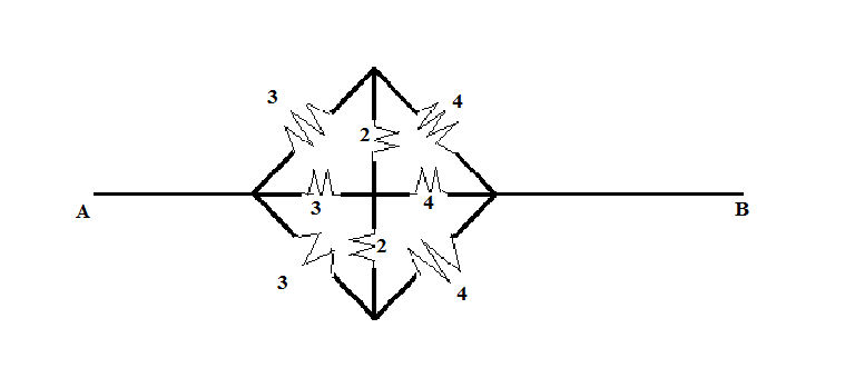
The equivalent resistance between A and B will be (in ohms)
 A. $\dfrac{2}{7}$
B. 8
C. $\dfrac{4}{3}$
D. $\dfrac{7}{3}$
Answer
621.6k+ views
Hint: In this question, we need to determine the equivalent resistance between terminal A and B in ohms. For this, we will use the property of the resistance connected in series as well as in parallel.
Complete step by step answer:
From the given circuit diagram, we can see that two resistances are connected to the node A of equal value, and so, we can say that the equal voltage drop will take place across both the resistances.
Similarly, we can see that two resistances are connected to the node B of equal value, and so, we can say that the equal voltage drop will take place across both the resistances.
Let the upper point where 3 ohms and 4 ohms meet be C so, the lower point where 3 ohms and 4 ohms meet will also be at the same potential. Hence, consider that point to be C as well.
Also, let the centre point be O.
Hence, the given circuit diagram (figure) will be reduced to
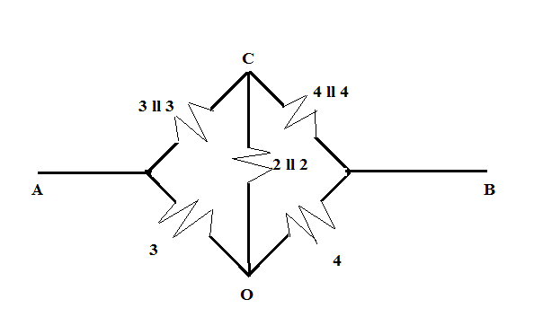
Here, the parallel equivalent of the resistances are calculated as
$3{\text{ II 3}} = \dfrac{{3 \times 3}}{{3 + 3}} = \dfrac{3}{2}$
Similarly,
${\text{4 II 4}} = \dfrac{{4 \times 4}}{{4 + 4}} = \dfrac{{16}}{8} = 2$
Again,
${\text{2 II 2}} = \dfrac{{2 \times 2}}{{2 + 2}} = \dfrac{4}{4} = 1$
So, the above-drawn figure is further reduced to
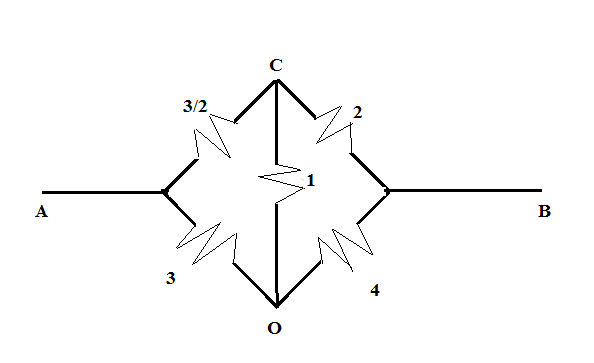
Now, from the above figure, we can see that the product of the resistances of the opposite sides of the bridge is equal such that $\dfrac{3}{2} \times 4 = 3 \times 2$. Hence, we can say that the bridge is balanced and so, no current will flow through the CO part of the circuit. Hence, the figure is further reduced to
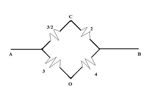 Now, we can see that $\dfrac{3}{2}$, and 2 ohms are connected in parallel with the series combination of the 3 and 4 ohms.
Hence, the equivalent resistance between the terminals A and B is given as:
$
R = \left( {\dfrac{3}{2} + 2} \right){\text{ ll }}\left( {3 + 4} \right) \\
= \left( {\dfrac{7}{2}} \right){\text{ ll }}7 \\
= \dfrac{{\dfrac{7}{2} \times 7}}{{\left( {\dfrac{7}{2} + 7} \right)}} \\
= \dfrac{{49}}{2} \times \dfrac{2}{{14 + 7}} \\
= \dfrac{{49}}{{21}} \\
= \dfrac{7}{3}\Omega \\
$
Therefore, the equivalent resistance between the terminals A and B is $\dfrac{7}{3}\Omega $
So, the correct answer is “Option D”.
Note:
In the complex circuit diagram (figure), we need to simplify the circuit using parallel and series combinations of the elements until we get the equivalent resistances. Moreover, the resistances connected across the same potential points; then, the resistances are known to be parallel connected.
Complete step by step answer:
From the given circuit diagram, we can see that two resistances are connected to the node A of equal value, and so, we can say that the equal voltage drop will take place across both the resistances.
Similarly, we can see that two resistances are connected to the node B of equal value, and so, we can say that the equal voltage drop will take place across both the resistances.
Let the upper point where 3 ohms and 4 ohms meet be C so, the lower point where 3 ohms and 4 ohms meet will also be at the same potential. Hence, consider that point to be C as well.
Also, let the centre point be O.
Hence, the given circuit diagram (figure) will be reduced to
Here, the parallel equivalent of the resistances are calculated as
$3{\text{ II 3}} = \dfrac{{3 \times 3}}{{3 + 3}} = \dfrac{3}{2}$
Similarly,
${\text{4 II 4}} = \dfrac{{4 \times 4}}{{4 + 4}} = \dfrac{{16}}{8} = 2$
Again,
${\text{2 II 2}} = \dfrac{{2 \times 2}}{{2 + 2}} = \dfrac{4}{4} = 1$
So, the above-drawn figure is further reduced to
Now, from the above figure, we can see that the product of the resistances of the opposite sides of the bridge is equal such that $\dfrac{3}{2} \times 4 = 3 \times 2$. Hence, we can say that the bridge is balanced and so, no current will flow through the CO part of the circuit. Hence, the figure is further reduced to
Hence, the equivalent resistance between the terminals A and B is given as:
$
R = \left( {\dfrac{3}{2} + 2} \right){\text{ ll }}\left( {3 + 4} \right) \\
= \left( {\dfrac{7}{2}} \right){\text{ ll }}7 \\
= \dfrac{{\dfrac{7}{2} \times 7}}{{\left( {\dfrac{7}{2} + 7} \right)}} \\
= \dfrac{{49}}{2} \times \dfrac{2}{{14 + 7}} \\
= \dfrac{{49}}{{21}} \\
= \dfrac{7}{3}\Omega \\
$
Therefore, the equivalent resistance between the terminals A and B is $\dfrac{7}{3}\Omega $
So, the correct answer is “Option D”.
Note:
In the complex circuit diagram (figure), we need to simplify the circuit using parallel and series combinations of the elements until we get the equivalent resistances. Moreover, the resistances connected across the same potential points; then, the resistances are known to be parallel connected.
Recently Updated Pages
Master Class 12 Business Studies: Engaging Questions & Answers for Success
Master Class 12 Chemistry: Engaging Questions & Answers for Success
Master Class 12 Biology: Engaging Questions & Answers for Success
Class 12 Question and Answer - Your Ultimate Solutions Guide
Master Class 11 English: Engaging Questions & Answers for Success
Master Class 11 Social Science: Engaging Questions & Answers for Success
Trending doubts
Which are the Top 10 Largest Countries of the World?
Draw a labelled sketch of the human eye class 12 physics CBSE
Differentiate between homogeneous and heterogeneous class 12 chemistry CBSE
Differentiate between Pyramid of energy and pyramid class 12 biology CBSE
Why is the cell called the structural and functional class 12 biology CBSE
Draw the diagram of the pyramid of energy Explain In class 12 biology CBSE