


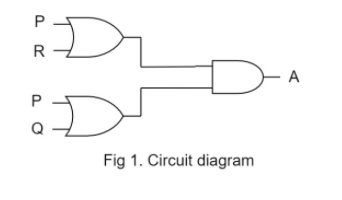
The diagram of a logic circuit is given below. The output A of the circuit is represented by:
A) $P.(R + Q)$
B) $P.(R.Q)$
C) $P + (R.Q)$
D) $P + (R + Q)$
Answer
625.5k+ views
Hint: Different gates represent different operations.
OR gate adds the input.
AND gate multiplies the input.
Fig1 depicts the problem in hand

Complete step by step solution:
Given:
1. Circuit diagram as given in circuit with inputs P, Q, R, and output A.
2. 2 OR gates and 1 AND.
To find: The expression for output A.
Step 1 of 3:
Find the out of upper OR gate, let it be X:
$X = P + R$
Find the out of lower OR gate, let it be Y:
$Y = P + Q$
Step 2 of 3:
Now X and Y are inputs to the AND gate.
$A = X \cdot Y$
Substitute the value of X and Y:
$A = (P + R) \cdot (P + Q)$
$
A = PP + PQ + RP + RQ \\
A = P(1 + Q) + RP + RQ \\
$
Step 3 of 3:
We know that the AND gate applied on 1 with any other input gives 1. This implies that $(1 + Q = 1)$:
$
A = P + R \cdot P + R \cdot Q \\
A = P(1 + R) + R \cdot Q \\
$
Again, we know that the AND gate applied on 1 with any other input gives 1. This implies that $(1 + R = 1)$:
$A = P + R \cdot Q$
The output A of the circuit is represented by $P + (R.Q)$. Hence the correct option is (C).
Note:
Logic gates are circuits made up of transistors and diodes as deciding components. It is these transistors that act as a switch, adder to the voltage signals applied through it. We commonly use RAM, in our PC, phone, etc. but all these are just a combination of flip flop logic gate circuits which enables us to store information. In questions like these, carefully look at the circuit diagram to identify the gates used. Apply proper operations corresponding to the gates.
OR gate adds the input.
AND gate multiplies the input.
Fig1 depicts the problem in hand
Complete step by step solution:
Given:
1. Circuit diagram as given in circuit with inputs P, Q, R, and output A.
2. 2 OR gates and 1 AND.
To find: The expression for output A.
Step 1 of 3:
Find the out of upper OR gate, let it be X:
$X = P + R$
Find the out of lower OR gate, let it be Y:
$Y = P + Q$
Step 2 of 3:
Now X and Y are inputs to the AND gate.
$A = X \cdot Y$
Substitute the value of X and Y:
$A = (P + R) \cdot (P + Q)$
$
A = PP + PQ + RP + RQ \\
A = P(1 + Q) + RP + RQ \\
$
Step 3 of 3:
We know that the AND gate applied on 1 with any other input gives 1. This implies that $(1 + Q = 1)$:
$
A = P + R \cdot P + R \cdot Q \\
A = P(1 + R) + R \cdot Q \\
$
Again, we know that the AND gate applied on 1 with any other input gives 1. This implies that $(1 + R = 1)$:
$A = P + R \cdot Q$
The output A of the circuit is represented by $P + (R.Q)$. Hence the correct option is (C).
Note:
Logic gates are circuits made up of transistors and diodes as deciding components. It is these transistors that act as a switch, adder to the voltage signals applied through it. We commonly use RAM, in our PC, phone, etc. but all these are just a combination of flip flop logic gate circuits which enables us to store information. In questions like these, carefully look at the circuit diagram to identify the gates used. Apply proper operations corresponding to the gates.
Recently Updated Pages
Master Class 12 Economics: Engaging Questions & Answers for Success
Master Class 12 English: Engaging Questions & Answers for Success
Master Class 12 Social Science: Engaging Questions & Answers for Success
Master Class 12 Maths: Engaging Questions & Answers for Success
Master Class 12 Physics: Engaging Questions & Answers for Success
Master Class 12 Business Studies: Engaging Questions & Answers for Success
Trending doubts
Which are the Top 10 Largest Countries of the World?
Draw a labelled sketch of the human eye class 12 physics CBSE
Differentiate between homogeneous and heterogeneous class 12 chemistry CBSE
Why is the cell called the structural and functional class 12 biology CBSE
Draw ray diagrams each showing i myopic eye and ii class 12 physics CBSE
Which is the correct genotypic ratio of mendel dihybrid class 12 biology CBSE