


The current through $ 10\Omega $ resistor as shown in fig is:
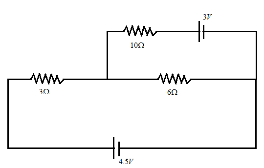
(A) $ 0.1A $
(B) $ 0.2A $
(C) $ 0.3A $
(D) $ zero $
Answer
564.9k+ views
Hint : Here, in this question we have been asked the current flowing through the resistor of $ 10\Omega $ . For this we have to study and use Kirchhoff's voltage law. It states that “in any closed loop network, the total voltage around the loop is equal to the sum of all the voltage drops within the same loop which is equal to zero”.
Complete Step By Step Answer:
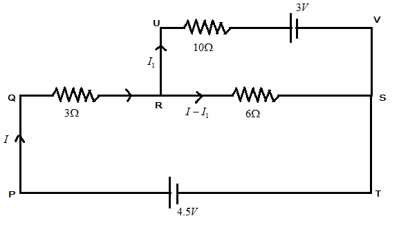
let us consider the above figure and name all the voltage drops and loops for our convenience as shown in figure below:
In the figure below, let us consider the loop as PQRST by applying Kirchhoff’s voltage law to this loop, we get
$ - 3I - 6(I - {I_1}) + 4.5 = 0 $
In the above equation,
$ - 3I $ is the voltage through resistor $ 3\Omega $ , $ - 6(I - {I_1}) $ is the voltage through the resistor $ 6\Omega $ and $ 4.5V $ is the voltage applied to the circuit.
$ - 9I + 6{I_1} + 4.5 = 0 $ ….. $ (1) $
Now let us consider the loop PQRUVT and applying Kirchhoff’s voltage law to this loop, we get
$ - 3I - 10{I_1} - 3 + 4.5 = 0 $
$ - 3I $ is the voltage through resistor $ 3\Omega $ , $ - 10{I_1} $ is the voltage through resistor $ 10\Omega $ and $ 4.5V $ is the voltage applied to the circuit along with $ 3V $ as the voltage applied in the loop RUVSR.
$ - 3I - 10{I_1} + 1.5 = 0 $ ….. $ (2) $
From $ (1) $ and $ (2) $ , we get
On solving both the equations we obtain the current flowing in resistor of $ 10\Omega $
$ {I_1} = 0 $
Hence, the current flowing through the resistor $ 10\Omega $ is $ zero $ .
Note :
We have calculated the current flowing through the resistor $ 10\Omega $ by using the Kirchhoff’s voltage law. We have used it and calculated the required answer. Voltage is the product of current and resistance through the circuit. Apply the law carefully and use the proper signs to indicate the directions of current along the circuit.
Complete Step By Step Answer:
let us consider the above figure and name all the voltage drops and loops for our convenience as shown in figure below:
In the figure below, let us consider the loop as PQRST by applying Kirchhoff’s voltage law to this loop, we get
$ - 3I - 6(I - {I_1}) + 4.5 = 0 $
In the above equation,
$ - 3I $ is the voltage through resistor $ 3\Omega $ , $ - 6(I - {I_1}) $ is the voltage through the resistor $ 6\Omega $ and $ 4.5V $ is the voltage applied to the circuit.
$ - 9I + 6{I_1} + 4.5 = 0 $ ….. $ (1) $
Now let us consider the loop PQRUVT and applying Kirchhoff’s voltage law to this loop, we get
$ - 3I - 10{I_1} - 3 + 4.5 = 0 $
$ - 3I $ is the voltage through resistor $ 3\Omega $ , $ - 10{I_1} $ is the voltage through resistor $ 10\Omega $ and $ 4.5V $ is the voltage applied to the circuit along with $ 3V $ as the voltage applied in the loop RUVSR.
$ - 3I - 10{I_1} + 1.5 = 0 $ ….. $ (2) $
From $ (1) $ and $ (2) $ , we get
On solving both the equations we obtain the current flowing in resistor of $ 10\Omega $
$ {I_1} = 0 $
Hence, the current flowing through the resistor $ 10\Omega $ is $ zero $ .
Note :
We have calculated the current flowing through the resistor $ 10\Omega $ by using the Kirchhoff’s voltage law. We have used it and calculated the required answer. Voltage is the product of current and resistance through the circuit. Apply the law carefully and use the proper signs to indicate the directions of current along the circuit.
Recently Updated Pages
Master Class 12 Economics: Engaging Questions & Answers for Success
Master Class 12 English: Engaging Questions & Answers for Success
Master Class 12 Social Science: Engaging Questions & Answers for Success
Master Class 12 Maths: Engaging Questions & Answers for Success
Master Class 12 Physics: Engaging Questions & Answers for Success
Master Class 9 General Knowledge: Engaging Questions & Answers for Success
Trending doubts
Which are the Top 10 Largest Countries of the World?
Draw a labelled sketch of the human eye class 12 physics CBSE
Differentiate between homogeneous and heterogeneous class 12 chemistry CBSE
Why is the cell called the structural and functional class 12 biology CBSE
Draw ray diagrams each showing i myopic eye and ii class 12 physics CBSE
Which is the correct genotypic ratio of mendel dihybrid class 12 biology CBSE