


The correct way of connecting the ammeter and voltmeter with a series combination of two resistors in a circuit for finding their equivalent is shown in the diagram.

A) A
B) B
C) C
D) D
Answer
579k+ views
Hint: Observe the four circuit diagram (A), (B), (C) and (D). After observing them, make sure that Ammeter is connected in series combination across electrical components and Voltmeter is connected in parallel combination. Check this fact with all the circuit diagrams and then evaluate the correct one.
Complete answer:
Given that two resistances ${{\text{R}}_{\text{1}}}$ and ${{\text{R}}_{\text{2}}}$ are connected in series combination along with Voltmeter and Ammeter.
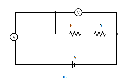
In circuit diagram (A), Ammeter is connected in parallel combination across resistances ${R_1}$ and ${R_2}$here, voltmeter is connected in series combination across resistances ${R_1}$ and ${R_2}$ but Ammeter is always connected in series combination and Voltmeter is connected in parallel combination.
So, connections made in figure (A) are incorrect.
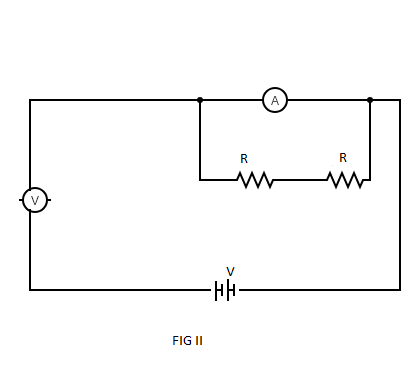
In circuit diagram (B), Ammeter is connected in series combination across resistances R1 and R2 and voltmeter is connected in parallel combination across resistances ${R_1}$ and ${R_2}$ .
As Ammeter is always connected in series combination and Voltmeter is connected in parallel combination.
So, connections made in figure (B) are correct.
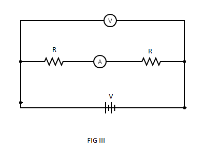
In circuit diagram (C), Ammeter is connected in between two resistances R1 and R2 and voltmeter is connected in parallel combination across resistances ${R_1}$ and ${R_2}$ .
As, Ammeter is always connected in series combination across electrical components and Voltmeter is connected in parallel combination.
Here, the connection of Voltmeter is correct but the connection of Ammeter is incorrect.
So, connections made in figure (C) are incorrect.
In circuit diagram (D), Ammeter is connected in parallel combination across resistances ${R_1}$ and ${R_2}$ and voltmeter is connected in series combination between two resistances ${R_1}$ and ${R_2}$ .
As, Ammeter is always connected in series combination across electrical components and Voltmeter is connected in parallel combination.
Here, the connection between Voltmeter and Ammeter is incorrect.
So, connections made in figure (D) are incorrect.
Therefore, option (B) is the correct choice.
Note:
Ammeter is always connected in series combination because the current flows through each and every component is same in the circuit. Resistance of the Ammeter is low. Voltmeter is used to measure the potential difference between two points in a circuit, Resistance of Voltmeter is high. However, resistors can be connected in series or in parallel combination.
Complete answer:
Given that two resistances ${{\text{R}}_{\text{1}}}$ and ${{\text{R}}_{\text{2}}}$ are connected in series combination along with Voltmeter and Ammeter.
In circuit diagram (A), Ammeter is connected in parallel combination across resistances ${R_1}$ and ${R_2}$here, voltmeter is connected in series combination across resistances ${R_1}$ and ${R_2}$ but Ammeter is always connected in series combination and Voltmeter is connected in parallel combination.
So, connections made in figure (A) are incorrect.
In circuit diagram (B), Ammeter is connected in series combination across resistances R1 and R2 and voltmeter is connected in parallel combination across resistances ${R_1}$ and ${R_2}$ .
As Ammeter is always connected in series combination and Voltmeter is connected in parallel combination.
So, connections made in figure (B) are correct.
In circuit diagram (C), Ammeter is connected in between two resistances R1 and R2 and voltmeter is connected in parallel combination across resistances ${R_1}$ and ${R_2}$ .
As, Ammeter is always connected in series combination across electrical components and Voltmeter is connected in parallel combination.
Here, the connection of Voltmeter is correct but the connection of Ammeter is incorrect.
So, connections made in figure (C) are incorrect.
In circuit diagram (D), Ammeter is connected in parallel combination across resistances ${R_1}$ and ${R_2}$ and voltmeter is connected in series combination between two resistances ${R_1}$ and ${R_2}$ .
As, Ammeter is always connected in series combination across electrical components and Voltmeter is connected in parallel combination.
Here, the connection between Voltmeter and Ammeter is incorrect.
So, connections made in figure (D) are incorrect.
Therefore, option (B) is the correct choice.
Note:
Ammeter is always connected in series combination because the current flows through each and every component is same in the circuit. Resistance of the Ammeter is low. Voltmeter is used to measure the potential difference between two points in a circuit, Resistance of Voltmeter is high. However, resistors can be connected in series or in parallel combination.
Recently Updated Pages
Master Class 12 Business Studies: Engaging Questions & Answers for Success
Master Class 12 Biology: Engaging Questions & Answers for Success
Master Class 12 Chemistry: Engaging Questions & Answers for Success
Class 12 Question and Answer - Your Ultimate Solutions Guide
Master Class 11 English: Engaging Questions & Answers for Success
Master Class 11 Social Science: Engaging Questions & Answers for Success
Trending doubts
Which are the Top 10 Largest Countries of the World?
Draw a labelled sketch of the human eye class 12 physics CBSE
Differentiate between homogeneous and heterogeneous class 12 chemistry CBSE
Why is the cell called the structural and functional class 12 biology CBSE
Draw ray diagrams each showing i myopic eye and ii class 12 physics CBSE
Which is the correct genotypic ratio of mendel dihybrid class 12 biology CBSE