


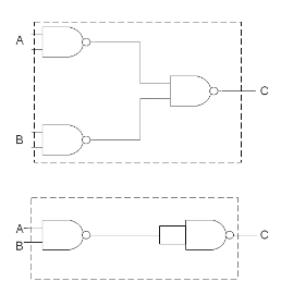
The combination of NAND gates shown hereunder are equivalent to
A) an OR gate and an AND gate respectively
B) an AND gate and a NOT gate respectively
C) an AND gate and an OR gate respectively
D) an OR gate and a NOT gate respectively
Answer
613.2k+ views
Hint: We need to write down the equation of the two circuits in question based on the gates used in it. Then using DeMorgan's theorem we need to simplify both the circuits into one gate for both the circuits. Then we will get the answer.
Formula used: In this solution we will be using the following formula,
DeMorgan’s theorem:
$\Rightarrow \overline {M.N} = \bar M + \bar N $
$\Rightarrow \overline {M + N} = \bar M\bar N $
Complete step by step solution:
To solve this circuit, let us write down the circuit equation of the output at C for the first circuit. The output of the first 2 NAND gates will be $ \bar A $ and $ \bar B $ . So the output at C will be,
$\Rightarrow C = \overline {\bar A + \bar B} $
Using the second identity of the DeMorgan’s theorem with $ M = \bar A $ and $ N = \bar B $ we can rewrite the above equation as:
$\Rightarrow C = \overline {\overline A } + \overline {\overline B } $
So we get,
$\Rightarrow C = A + B $
Which corresponds to an OR gate for the first circuit.
Similarly, for the second circuit, we can write the output of the first NAND gate as, $ \overline {A \cdot B} $ . So the output at C can be written as
$\Rightarrow C = \overline {\overline {AB.} \overline {AB} } $
Using the first identity of the DeMorgan’s theorem with $ M = \overline {AB} $ and $ N = \overline {AB} $ , we can write
$\Rightarrow C = \overline {\overline {AB} } + \overline {\overline {AB} } $
So we get,
$\Rightarrow C = AB + AB $
Since the addition (OR) of the two same inputs is equal to the input itself, we have
$\Rightarrow C = AB $ which corresponds to an AND gate.
Since the first circuit is an OR gate and the second circuit is equivalent to AND gate, the correct choice is option (A).
Note:
We must be familiar with the identities of DeMorgan's theorem to break such circuits down into simpler forms. Alternatively, we can also form a logic table for both the circuits and determine the kind of gates. So, for the first circuit, the logic table would be
Which corresponds to an OR gate.
And the logic table of the second circuit would be
Which corresponds to an AND gate.
Formula used: In this solution we will be using the following formula,
DeMorgan’s theorem:
$\Rightarrow \overline {M.N} = \bar M + \bar N $
$\Rightarrow \overline {M + N} = \bar M\bar N $
Complete step by step solution:
To solve this circuit, let us write down the circuit equation of the output at C for the first circuit. The output of the first 2 NAND gates will be $ \bar A $ and $ \bar B $ . So the output at C will be,
$\Rightarrow C = \overline {\bar A + \bar B} $
Using the second identity of the DeMorgan’s theorem with $ M = \bar A $ and $ N = \bar B $ we can rewrite the above equation as:
$\Rightarrow C = \overline {\overline A } + \overline {\overline B } $
So we get,
$\Rightarrow C = A + B $
Which corresponds to an OR gate for the first circuit.
Similarly, for the second circuit, we can write the output of the first NAND gate as, $ \overline {A \cdot B} $ . So the output at C can be written as
$\Rightarrow C = \overline {\overline {AB.} \overline {AB} } $
Using the first identity of the DeMorgan’s theorem with $ M = \overline {AB} $ and $ N = \overline {AB} $ , we can write
$\Rightarrow C = \overline {\overline {AB} } + \overline {\overline {AB} } $
So we get,
$\Rightarrow C = AB + AB $
Since the addition (OR) of the two same inputs is equal to the input itself, we have
$\Rightarrow C = AB $ which corresponds to an AND gate.
Since the first circuit is an OR gate and the second circuit is equivalent to AND gate, the correct choice is option (A).
Note:
We must be familiar with the identities of DeMorgan's theorem to break such circuits down into simpler forms. Alternatively, we can also form a logic table for both the circuits and determine the kind of gates. So, for the first circuit, the logic table would be
| Input | Input | Output |
| A | B | C |
| 0 | 0 | 0 |
| 1 | 0 | 1 |
| 0 | 1 | 1 |
| 1 | 1 | 1 |
Which corresponds to an OR gate.
And the logic table of the second circuit would be
| Input | Input | Output |
| A | B | C |
| 0 | 0 | 0 |
| 1 | 0 | 0 |
| 0 | 1 | 0 |
| 1 | 1 | 1 |
Which corresponds to an AND gate.
Recently Updated Pages
Master Class 12 Business Studies: Engaging Questions & Answers for Success
Master Class 12 Chemistry: Engaging Questions & Answers for Success
Master Class 12 Biology: Engaging Questions & Answers for Success
Class 12 Question and Answer - Your Ultimate Solutions Guide
Master Class 11 English: Engaging Questions & Answers for Success
Master Class 11 Social Science: Engaging Questions & Answers for Success
Trending doubts
Which are the Top 10 Largest Countries of the World?
Draw a labelled sketch of the human eye class 12 physics CBSE
Differentiate between homogeneous and heterogeneous class 12 chemistry CBSE
Differentiate between Pyramid of energy and pyramid class 12 biology CBSE
Why is the cell called the structural and functional class 12 biology CBSE
Draw the diagram of the pyramid of energy Explain In class 12 biology CBSE