


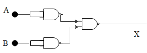
The combination of gates shown below yields
(A) OR gate
(B) NOT gate
(C) XOR gate
(D) NAND gate
Answer
590.7k+ views
Hint: All other digital circuits are made up of these three basic logic gates. Hence, NAND gate is a combination of AND and NOT gate. In other words, the output of the AND gate is connected to the input of the NOT gate. Thus the output of NAND gate is opposite to AND gate. When two inputs of a NAND gate are shorted, the resulting circuit acts as a NOT gate. Hence in the given figure the input A and B are connected to a NOT gate and the resulting output of both the NOT gate is given to a NAND gate.
Complete step by step answer:
A logic gate is a digital circuit with one or input signal but only one output signal. There are three basic logic gates. All digital circuits are made with these three gates. That is, AND gate, OR gate and NOT gate.
An OR gate is a logic circuit that has two or more inputs but only one output. The output of an OR gate is high, if any or all the inputs are high. Similarly, AND gate is a logic circuit that has two or more inputs and one output. The output of an AND gate shows high when all the inputs are high. However, the output of the AND gate is low if any or all inputs are low. NOT gate or inverter is the simplest of all logic gates. It has only one input and one output. The NOT gate is also called an inverter because it inverts the input.
All other digital circuits are made up of these three basic logic gates. Hence, NAND gate is a combination of AND and NOT gate. In other words, output of AND gate is connected to the input of NOT gate. Thus the output of NAND gate is opposite to AND gate.
The Boolean expression of NAND gate is,
$Y=\overline{A.B}$
where, $Y=A.B$ is the Boolean expression of AND gate and Y is the output.
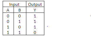
Truth table of NAND gate given by,
NAND gate is a universal gate because its repeated use can produce other logic gates like AND, OR and NOT.
When two inputs of a NAND gate are shorted, the resulting circuit acts as a NOT gate. Hence in the given figure the input A and B are connected to a NOT gate and the resulting output of both the NOT gate is given to a NAND gate.
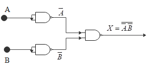
$\therefore X=\overline{\overline{A}.\overline{B}}$ …….(1)
According to De Morgan’s theorem,
$\overline{A.B}=\overline{A}+\overline{B}$
Applying De Morgan’s theorem in equation (1),
$X=\overline{\overline{A}}+\overline{\overline{B}}=A+B$
Hence, the resultant gate is OR gate.
Thus option(A) is correct.
Note:
All other digital circuits are made up of these three basic logic gates. Hence, NAND gate is a combination of AND and NOT gate. In other words, output of AND gate is connected to the input of NOT gate. Thus the output of NAND gate is opposite to AND gate. NAND gate is a universal gate because its repeated use can produce other logic gates like AND, OR and NOT.
Complete step by step answer:
A logic gate is a digital circuit with one or input signal but only one output signal. There are three basic logic gates. All digital circuits are made with these three gates. That is, AND gate, OR gate and NOT gate.
An OR gate is a logic circuit that has two or more inputs but only one output. The output of an OR gate is high, if any or all the inputs are high. Similarly, AND gate is a logic circuit that has two or more inputs and one output. The output of an AND gate shows high when all the inputs are high. However, the output of the AND gate is low if any or all inputs are low. NOT gate or inverter is the simplest of all logic gates. It has only one input and one output. The NOT gate is also called an inverter because it inverts the input.
All other digital circuits are made up of these three basic logic gates. Hence, NAND gate is a combination of AND and NOT gate. In other words, output of AND gate is connected to the input of NOT gate. Thus the output of NAND gate is opposite to AND gate.
The Boolean expression of NAND gate is,
$Y=\overline{A.B}$
where, $Y=A.B$ is the Boolean expression of AND gate and Y is the output.
Truth table of NAND gate given by,
NAND gate is a universal gate because its repeated use can produce other logic gates like AND, OR and NOT.
When two inputs of a NAND gate are shorted, the resulting circuit acts as a NOT gate. Hence in the given figure the input A and B are connected to a NOT gate and the resulting output of both the NOT gate is given to a NAND gate.
$\therefore X=\overline{\overline{A}.\overline{B}}$ …….(1)
According to De Morgan’s theorem,
$\overline{A.B}=\overline{A}+\overline{B}$
Applying De Morgan’s theorem in equation (1),
$X=\overline{\overline{A}}+\overline{\overline{B}}=A+B$
Hence, the resultant gate is OR gate.
Thus option(A) is correct.
Note:
All other digital circuits are made up of these three basic logic gates. Hence, NAND gate is a combination of AND and NOT gate. In other words, output of AND gate is connected to the input of NOT gate. Thus the output of NAND gate is opposite to AND gate. NAND gate is a universal gate because its repeated use can produce other logic gates like AND, OR and NOT.
Recently Updated Pages
Master Class 12 Social Science: Engaging Questions & Answers for Success
Master Class 12 Physics: Engaging Questions & Answers for Success
Master Class 12 Maths: Engaging Questions & Answers for Success
Master Class 12 Economics: Engaging Questions & Answers for Success
Master Class 12 Chemistry: Engaging Questions & Answers for Success
Master Class 12 Business Studies: Engaging Questions & Answers for Success
Trending doubts
Which are the Top 10 Largest Countries of the World?
Draw a labelled sketch of the human eye class 12 physics CBSE
Explain the structure of megasporangium class 12 biology CBSE
What are the major means of transport Explain each class 12 social science CBSE
How many chromosomes are found in human ovum a 46 b class 12 biology CBSE
The diagram of the section of a maize grain is given class 12 biology CBSE