


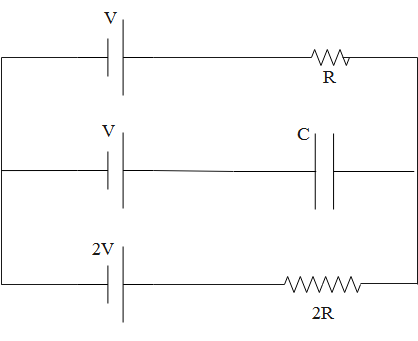
The circuit shown in figure is in steady state. What will be the potential difference across the capacitor?
A. $V$
B. $\dfrac{V}{2}$
C. $\dfrac{V}{3}$
D. $\dfrac{2V}{3}$
Answer
600k+ views
Hint: To solve this problem, first assume the direction of current in each branch and label accordingly. Then, use Kirchhoff’s Voltage Law along closed loops and Kirchhoff’s Current law at the junction.
According to KVL, “the algebraic sum of all voltages within the loop must be equal to zero.”
According to Kirchhoff’s Current Law or KCL the total current entering at junction is exactly equal to the electric current leaving the node.
Complete answer:
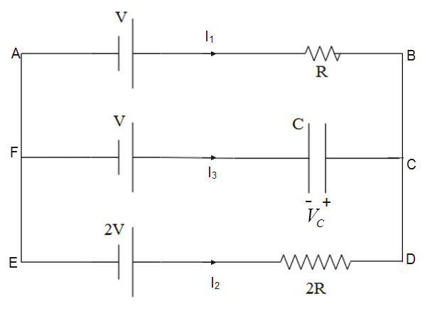
First, we name the connecting points as shown in figure below. We have assumed that current flowing along AB, ED and FC is ${{I}_{1}},\,{{I}_{2}}$ and ${{I}_{3}}$ respectively.
According to Kirchhoff’s Voltage Law or KVL, “in any closed loop network, the total potential difference around the loop is equal to the sum of all the potential drops within the same loop is equal to zero. In other words, “the algebraic sum of all voltages within the loop must be equal to zero.”
So, moving along the loop ABDEA, we have
$-V+{{I}_{1}}R-2{{I}_{3}}R+2V$
On simplifying this equation, we get
$V=(2{{I}_{3}}-{{I}_{1}})R$
According to Kirchhoff’s Current Law or KCL the total current entering at junction is exactly equal to the electric current leaving the node. Therefore, at node C, we have
${{I}_{1}}+{{I}_{2}}+{{I}_{3}}=0$
Since, ${{I}_{3}}=0$, we have
${{I}_{1}}=-{{I}_{3}}$
Substituting this value in expression obtained for voltage, we get
$V=(2{{I}_{3}}-(-{{I}_{1}}))R=3{{I}_{3}}R$
This implies that
${{I}_{3}}R=\dfrac{V}{3}$
Let’s assume that potential difference across the capacitor is ${{V}_{C}}$, then applying KVL along the loop CDEF, we get
$-2{{I}_{3}}R+2V-V-{{V}_{C}}=0$
Substituting ${{I}_{3}}R=\dfrac{V}{3}$, the above equation becomes
$-\dfrac{2V}{3}+2V-V-{{V}_{C}}$
On rearranging and simplifying, we get potential difference across the capacitor as
${{V}_{C}}=\dfrac{V}{3}$
So, the correct answer is “Option C”.
Note:
Kirchhoff’s laws can be used to solve most of the problems related to electric circuits.
While using Kirchhoff’s laws, signs must be used according to convention. Otherwise, students may arrive at the wrong results.
The direction of current, we assume, does not affect the magnitude of current. If we assume the direction of current in the opposite direction of its actual direction, the magnitude of current obtained will be negative.
According to KVL, “the algebraic sum of all voltages within the loop must be equal to zero.”
According to Kirchhoff’s Current Law or KCL the total current entering at junction is exactly equal to the electric current leaving the node.
Complete answer:
First, we name the connecting points as shown in figure below. We have assumed that current flowing along AB, ED and FC is ${{I}_{1}},\,{{I}_{2}}$ and ${{I}_{3}}$ respectively.
According to Kirchhoff’s Voltage Law or KVL, “in any closed loop network, the total potential difference around the loop is equal to the sum of all the potential drops within the same loop is equal to zero. In other words, “the algebraic sum of all voltages within the loop must be equal to zero.”
So, moving along the loop ABDEA, we have
$-V+{{I}_{1}}R-2{{I}_{3}}R+2V$
On simplifying this equation, we get
$V=(2{{I}_{3}}-{{I}_{1}})R$
According to Kirchhoff’s Current Law or KCL the total current entering at junction is exactly equal to the electric current leaving the node. Therefore, at node C, we have
${{I}_{1}}+{{I}_{2}}+{{I}_{3}}=0$
Since, ${{I}_{3}}=0$, we have
${{I}_{1}}=-{{I}_{3}}$
Substituting this value in expression obtained for voltage, we get
$V=(2{{I}_{3}}-(-{{I}_{1}}))R=3{{I}_{3}}R$
This implies that
${{I}_{3}}R=\dfrac{V}{3}$
Let’s assume that potential difference across the capacitor is ${{V}_{C}}$, then applying KVL along the loop CDEF, we get
$-2{{I}_{3}}R+2V-V-{{V}_{C}}=0$
Substituting ${{I}_{3}}R=\dfrac{V}{3}$, the above equation becomes
$-\dfrac{2V}{3}+2V-V-{{V}_{C}}$
On rearranging and simplifying, we get potential difference across the capacitor as
${{V}_{C}}=\dfrac{V}{3}$
So, the correct answer is “Option C”.
Note:
Kirchhoff’s laws can be used to solve most of the problems related to electric circuits.
While using Kirchhoff’s laws, signs must be used according to convention. Otherwise, students may arrive at the wrong results.
The direction of current, we assume, does not affect the magnitude of current. If we assume the direction of current in the opposite direction of its actual direction, the magnitude of current obtained will be negative.
Recently Updated Pages
Three beakers labelled as A B and C each containing 25 mL of water were taken A small amount of NaOH anhydrous CuSO4 and NaCl were added to the beakers A B and C respectively It was observed that there was an increase in the temperature of the solutions contained in beakers A and B whereas in case of beaker C the temperature of the solution falls Which one of the following statements isarecorrect i In beakers A and B exothermic process has occurred ii In beakers A and B endothermic process has occurred iii In beaker C exothermic process has occurred iv In beaker C endothermic process has occurred
Master Class 12 Social Science: Engaging Questions & Answers for Success
Master Class 12 Physics: Engaging Questions & Answers for Success
Master Class 12 Maths: Engaging Questions & Answers for Success
Master Class 12 Economics: Engaging Questions & Answers for Success
Master Class 12 Chemistry: Engaging Questions & Answers for Success
Three beakers labelled as A B and C each containing 25 mL of water were taken A small amount of NaOH anhydrous CuSO4 and NaCl were added to the beakers A B and C respectively It was observed that there was an increase in the temperature of the solutions contained in beakers A and B whereas in case of beaker C the temperature of the solution falls Which one of the following statements isarecorrect i In beakers A and B exothermic process has occurred ii In beakers A and B endothermic process has occurred iii In beaker C exothermic process has occurred iv In beaker C endothermic process has occurred
Master Class 12 Social Science: Engaging Questions & Answers for Success
Master Class 12 Physics: Engaging Questions & Answers for Success
Trending doubts
Which are the Top 10 Largest Countries of the World?
Draw a labelled sketch of the human eye class 12 physics CBSE
Differentiate between homogeneous and heterogeneous class 12 chemistry CBSE
What are the major means of transport Explain each class 12 social science CBSE
Sulphuric acid is known as the king of acids State class 12 chemistry CBSE
Why should a magnesium ribbon be cleaned before burning class 12 chemistry CBSE