


The circuit is equivalent to
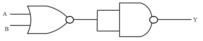
(1) NOR gate
(2) OR gate
(3) AND gate
(4) NAND gate
Answer
506.7k+ views
Hint:The circuit has a NOR gate, a NAND gate according to the question. The input is sent to the NOR gate, whose output becomes the input for the NAND gate, and the NAND gate's output becomes the final output. This will help you in answering this question.
Complete step-by-step solution:
Taking outputs of all the gates as ${{y}_{1}},{{y}_{2}}$,
(1) In a NOR gate, the output is the inverse of the sum of A and B. (NOR, OUTPUT $=\overline{A+B}$ ).
(2) In a NAND gate, the output is the inverse of the multiplication of A and B. (NAND, OUTPUT $=\overline{A \cdot B}$ ).
We know that a NOR gate inverses the sum of its inputs, so output at NOR is $y_{1}=\overline{A+B}$
$y_{1}$ becomes the input for NAND gate, so,
$\overline{y_{1} \cdot y_{1}}=y_{2}=\overline{\overline{A+B} \cdot \overline{A+B}}=\overline{\overline{A+B}}+\overline{\overline{A+B}}=A+B$
This will be the final output for the combination of the gates.
That is,
$Y=A+B$
This is the output we obtain for an OR gate. Therefore the correct option is (2).
Note: The small circle beside each of the gates makes them NOR and NAND gates, so don't get them mixed up with the diagram. It is the polar opposite of OR and AND. The N stands for "negation of," which means the opposite. The NOR gate is a digital logic gate that implements logical NOR; it acts in accordance with the truth table on the right.
Recently Updated Pages
Master Class 12 Economics: Engaging Questions & Answers for Success
Master Class 12 Physics: Engaging Questions & Answers for Success
Master Class 12 English: Engaging Questions & Answers for Success
Master Class 12 Social Science: Engaging Questions & Answers for Success
Master Class 12 Maths: Engaging Questions & Answers for Success
Master Class 12 Business Studies: Engaging Questions & Answers for Success
Trending doubts
Which are the Top 10 Largest Countries of the World?
What are the major means of transport Explain each class 12 social science CBSE
Draw a labelled sketch of the human eye class 12 physics CBSE
Why cannot DNA pass through cell membranes class 12 biology CBSE
Differentiate between insitu conservation and exsitu class 12 biology CBSE
Draw a neat and well labeled diagram of TS of ovary class 12 biology CBSE