


The average value of output direct current in a half wave rectifier is
$\begin{align}
& a)\dfrac{{{I}_{0}}}{\pi } \\
& b)\dfrac{{{I}_{0}}}{2} \\
& c)\dfrac{\pi {{I}_{0}}}{2} \\
& d)\dfrac{2{{I}_{0}}}{\pi } \\
\end{align}$
Answer
626.1k+ views
Hint: A half wave rectifier filters the negative cycle of the AC input and only allows the generated output as the positive half cycles of AC. The average value of output direct current in a half wave rectifier is given as the area under the curve of the cycle full cycle of the input AC divided by the base. Hence will integrate the area of the curve of the half cycle after the rectification and obtain the average value of DC current.
Complete step-by-step answer:
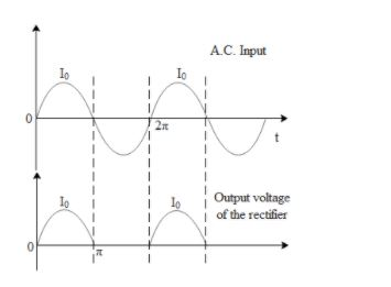
In the above figure we can clearly see how the output voltage is generated by the half wave rectifier. The average value of DC current is mathematically represented as,
${{I}_{DC}}=\int\limits_{0}^{2\pi }{\dfrac{id\theta }{2\pi }}$ where i is the AC current over a small interval $d\theta $.Now in the case of a half wave rectifier, the current exists between the interval of $\text{0 to }\!\!\pi\!\!\text{ }\text{.}$ Hence the Dc current for a half wave rectifier is given by,
${{I}_{DC}}=\int\limits_{0}^{\pi }{\dfrac{id\theta }{2\pi }}$ . The current i in an AC circuit is mathematically represented as, $i={{I}_{0}}\operatorname{Sin}\theta $ where ${{I}_{0}}$is the maximum current in the circuit and $\theta $is the interval at which i is its corresponding instantaneous current. Hence the equation for average DC current in a half wave rectifier becomes,
$\begin{align}
& {{I}_{DC}}=\int\limits_{0}^{\pi }{\dfrac{{{I}_{0}}\operatorname{Sin}\theta d\theta }{2\pi }}\text{,after integrating} \\
& {{I}_{DC}}=\dfrac{{{I}_{0}}}{2\pi }\left[ -\operatorname{Cos}\theta \right]_{0}^{\pi } \\
& {{I}_{DC}}=-\dfrac{{{I}_{0}}}{2\pi }\left[ \operatorname{Cos}\pi -\operatorname{Cos}0 \right] \\
& {{I}_{DC}}=-\dfrac{{{I}_{0}}}{2\pi }\left[ -1-1 \right] \\
& {{I}_{DC}}=\dfrac{2{{I}_{0}}}{2\pi }=\dfrac{{{I}_{0}}}{\pi } \\
\end{align}$
So, the correct answer is “Option A”.
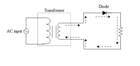
Note: In the above waveform of the half wave rectifier we can see that the current only flows through the load resistor(output ) only during the positive half cycle of AC. This is because it consists of a diode which only allows the flow of current in the forward bias state. When the negative cycle of AC tries to enter the diode it becomes reversed biased and hence does not allow the flow of current. Given below is a circuit diagram of a half wave rectifier.
Complete step-by-step answer:
In the above figure we can clearly see how the output voltage is generated by the half wave rectifier. The average value of DC current is mathematically represented as,
${{I}_{DC}}=\int\limits_{0}^{2\pi }{\dfrac{id\theta }{2\pi }}$ where i is the AC current over a small interval $d\theta $.Now in the case of a half wave rectifier, the current exists between the interval of $\text{0 to }\!\!\pi\!\!\text{ }\text{.}$ Hence the Dc current for a half wave rectifier is given by,
${{I}_{DC}}=\int\limits_{0}^{\pi }{\dfrac{id\theta }{2\pi }}$ . The current i in an AC circuit is mathematically represented as, $i={{I}_{0}}\operatorname{Sin}\theta $ where ${{I}_{0}}$is the maximum current in the circuit and $\theta $is the interval at which i is its corresponding instantaneous current. Hence the equation for average DC current in a half wave rectifier becomes,
$\begin{align}
& {{I}_{DC}}=\int\limits_{0}^{\pi }{\dfrac{{{I}_{0}}\operatorname{Sin}\theta d\theta }{2\pi }}\text{,after integrating} \\
& {{I}_{DC}}=\dfrac{{{I}_{0}}}{2\pi }\left[ -\operatorname{Cos}\theta \right]_{0}^{\pi } \\
& {{I}_{DC}}=-\dfrac{{{I}_{0}}}{2\pi }\left[ \operatorname{Cos}\pi -\operatorname{Cos}0 \right] \\
& {{I}_{DC}}=-\dfrac{{{I}_{0}}}{2\pi }\left[ -1-1 \right] \\
& {{I}_{DC}}=\dfrac{2{{I}_{0}}}{2\pi }=\dfrac{{{I}_{0}}}{\pi } \\
\end{align}$
So, the correct answer is “Option A”.
Note: In the above waveform of the half wave rectifier we can see that the current only flows through the load resistor(output ) only during the positive half cycle of AC. This is because it consists of a diode which only allows the flow of current in the forward bias state. When the negative cycle of AC tries to enter the diode it becomes reversed biased and hence does not allow the flow of current. Given below is a circuit diagram of a half wave rectifier.
Recently Updated Pages
Master Class 12 Business Studies: Engaging Questions & Answers for Success
Master Class 12 Chemistry: Engaging Questions & Answers for Success
Master Class 12 Biology: Engaging Questions & Answers for Success
Class 12 Question and Answer - Your Ultimate Solutions Guide
Master Class 11 English: Engaging Questions & Answers for Success
Master Class 11 Social Science: Engaging Questions & Answers for Success
Trending doubts
Differentiate between Pyramid of energy and pyramid class 12 biology CBSE
Draw the diagram of the pyramid of energy Explain In class 12 biology CBSE
What is the Full Form of PVC, PET, HDPE, LDPE, PP and PS ?
The first microscope was invented by A Leeuwenhoek class 12 biology CBSE
Suicide bags of cells are aEndoplasmic reticulum bLysosome class 12 biology CBSE
Loss of upper fertile layer of soil is known as APedogenesis class 12 biology CBSE