


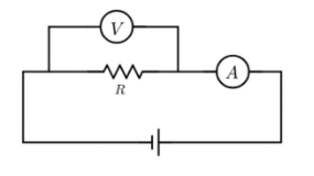
The actual value of resistance R shown in the figure is $20\Omega$. This is measured is an experiment as shown using the standard formula $R=\dfrac{V}{I}$, where V and I are the readings of the voltmeter and ammeter respectively. If the measured value of R is $10\%$ less, then the internal resistance of the voltmeter is (in ohms)? (Neglect resistance of ammeter).
Answer
559.2k+ views
Hint: First determine the measured effective resistance value of the circuit given that it is $10\%$ less than the actual value. Then, obtain an expression for the effective resistance of the circuit which involves the resistor and the voltmeter being parallel to each other. Equate the two expressions and arithmetically solve for the internal resistance of the voltmeter.
Formula Used:
Effective resistance of two resistors in parallel: $R_{eff} = \dfrac{R_1 R_2}{R_1 +R_2}$
Complete Step-by-Step Solution:
We are given that the actual value of resistance R is $20\Omega$.
But the measured value is $10\%$ less than the actual value, i.e.,
$R_{measured} = R - \dfrac{10}{100}R = R-0.1R = 0.9R$
$\Rightarrow R_{measured} = 0.9 \times 20 = 18\Omega$.
We are given that this reduction in the measured value is due to the internal resistance $R_V$ of the voltmeter (we neglect resistance of ammeter). The voltmeter V and the resistance R are connected in parallel to each other. We can solve for the internal resistance of the voltmeter by obtaining an expression for the effective resistance of the voltmeter and the resistor, i.e.,
$R_{eff} = \dfrac{R\times R_V}{R+R_V}$.
But we know that the effective resistance of the setup is the measured value of the resistance, i.e.,
$\Rightarrow R_{measured} = \dfrac{R\times R_V}{R+R_V}$
$\Rightarrow 18 = \dfrac{20R_V}{20+R_V}$
$\Rightarrow 18(20+R_V) = 20R_V$
$\Rightarrow 20R_V – 18R_V=360$
$R_V = \dfrac{360}{2} = 180\Omega$
Therefore, the internal resistance of the voltmeter is found to be $180\;ohms$.
Note:
Remember that a series circuit is a voltage divider whereas a parallel circuit is a current divider. We add up all the resistances in a series circuit because the resistances are arranged in such a way that the current has only one path to take. However, when resistances are connected in parallel, there are multiple paths for the current to pass through but have the same potential difference across them. This results in a net resistance that is lower than any of the individual resistances.
This is also the same reason why the voltmeter might read a lower voltage if a resistance is connected in parallel to it. This is because the internal resistance of the voltmeter is generally very high and if a relatively low resistance is introduced in a parallel branch, most of the current gets diverted to the path of least resistance and the voltmeter receives relatively lesser current and is thus able to process it and show a lesser voltage.
Recently Updated Pages
Master Class 12 Economics: Engaging Questions & Answers for Success
Master Class 12 Physics: Engaging Questions & Answers for Success
Master Class 12 English: Engaging Questions & Answers for Success
Master Class 12 Social Science: Engaging Questions & Answers for Success
Master Class 12 Maths: Engaging Questions & Answers for Success
Master Class 12 Business Studies: Engaging Questions & Answers for Success
Trending doubts
Which are the Top 10 Largest Countries of the World?
What are the major means of transport Explain each class 12 social science CBSE
Draw a labelled sketch of the human eye class 12 physics CBSE
Why cannot DNA pass through cell membranes class 12 biology CBSE
Differentiate between insitu conservation and exsitu class 12 biology CBSE
Draw a neat and well labeled diagram of TS of ovary class 12 biology CBSE