


Symbol in the figure represents.

A. Voltmeter
B. Ammeter
C. Alternating current source
D. Direct current source
Answer
573.9k+ views
Hint: While drawing electric circuits, we come across various symbols for different quantities. Voltmeter, if you may recall, is used to measure voltage in a circuit, similarly ammeter is used to measure current, alternating current source is the source that alternates its magnitude and direction continuously and direct current source is the source that produces unidirectional flow of charges. Now you may recall the symbols for each source and hence identify the above symbol.
Complete step-by-step answer:
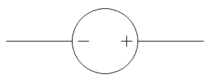
The symbol given in the question represents an alternating current source.
By alternating current we mean that electric current that periodically reverses direction and changes its magnitude continuously. The waveform representing alternating current in most electric power circuits is a sine wave that contains both positive and negative half periods. The positive half period corresponds to the positive direction of current and the negative half-period corresponds to the negative direction of current. If you look at the given symbol carefully, you may find that the above mentioned waveform is being symbolized in it.
Therefore, we find that the given symbol represents an alternating current source. Hence, the answer to the question is option C.
So, the correct answer is “Option C”.
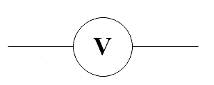
Note: Now that we have identified the above symbol, let us find the symbols representing the other options. Voltmeter can be represented by,
Ammeter can be represented by,

DC source can be represented by,
Also, if you didn’t know, the electric power delivered to our residences is in the form of alternating current.
Complete step-by-step answer:
The symbol given in the question represents an alternating current source.
By alternating current we mean that electric current that periodically reverses direction and changes its magnitude continuously. The waveform representing alternating current in most electric power circuits is a sine wave that contains both positive and negative half periods. The positive half period corresponds to the positive direction of current and the negative half-period corresponds to the negative direction of current. If you look at the given symbol carefully, you may find that the above mentioned waveform is being symbolized in it.
Therefore, we find that the given symbol represents an alternating current source. Hence, the answer to the question is option C.
So, the correct answer is “Option C”.
Note: Now that we have identified the above symbol, let us find the symbols representing the other options. Voltmeter can be represented by,
Ammeter can be represented by,
DC source can be represented by,
Also, if you didn’t know, the electric power delivered to our residences is in the form of alternating current.
Recently Updated Pages
Master Class 12 Economics: Engaging Questions & Answers for Success
Master Class 12 Physics: Engaging Questions & Answers for Success
Master Class 12 English: Engaging Questions & Answers for Success
Master Class 12 Social Science: Engaging Questions & Answers for Success
Master Class 12 Maths: Engaging Questions & Answers for Success
Master Class 12 Business Studies: Engaging Questions & Answers for Success
Trending doubts
Which are the Top 10 Largest Countries of the World?
What are the major means of transport Explain each class 12 social science CBSE
Draw a labelled sketch of the human eye class 12 physics CBSE
Why cannot DNA pass through cell membranes class 12 biology CBSE
Differentiate between insitu conservation and exsitu class 12 biology CBSE
Draw a neat and well labeled diagram of TS of ovary class 12 biology CBSE