


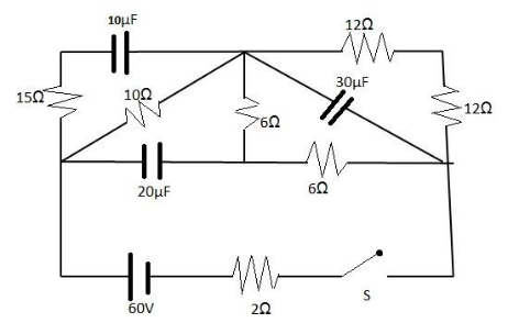
Switch S is closed at $ t = 0 $ , $ {I_{10}} $ is the current supplied by the battery just after closing the switch S. $ {Q_1} $ , $ {Q_2} $ and $ {Q_3} $ are the charges on the capacitors of $ 10\mu F $ , $ 20\mu F $ and $ 30\mu F $ in steady state respectively. $ {I_{20}} $ is the current supplied by the battery in the circuit at steady state. Choose the correct statement(s).
(A) $ {I_{10}} > {I_{20}} $
(B) $ {I_{10}} < {I_{20}} $
(C) $ {Q_1} < {Q_2} < {Q_3} $
(D) $ {Q_1} < {Q_3} < {Q_2} $
Answer
580.8k+ views
Hint: No current was flowing through the capacitors before the switch was closed at $ t = 0 $ . We know that current is the flow of charge.
Formula Used: The formulae used in the solution are given here.
Current $ I = C\dfrac{{dV}}{{dt}} $ , where $ C $ the capacitance in Farad and voltage across the capacitor is $ V $ .
Charge on the capacitor, $ Q = CV $ .
Complete Step by Step Solution
No flow of charge to and from the capacitors plates was zero, prior to $ t = 0 $ . Hence as charge on capacitor plates varies proportionally with the voltage across them, therefore voltage across them is zero before $ t = 0 $ . We can say that the capacitor was short circuited or it behaved as if it was being short circuited.
We know, current through capacitor, $ I $ and voltage across the capacitor, $ V $ , is related as
$ I = C\dfrac{{dV}}{{dt}} $ , where $ C $ is the capacitance in Farad.
Following from the above, when the switch is turned on at $ t = 0 $ , the capacitor behaves as being short circuited , for the initial time being.
The circuit thus looks like,
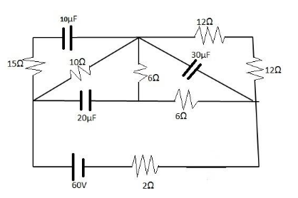
On solving, we see that the resistances $ 10\Omega $ , $ 6\Omega $ , $ 15\Omega $ , $ 6\Omega $ are in parallel. So equivalent resistance,
$ \dfrac{1}{{{R_{eq}}}} = \dfrac{1}{{10}} + \dfrac{1}{6} + \dfrac{1}{{15}} + \dfrac{1}{6} $
$ \Rightarrow \dfrac{1}{{{R_{eq}}}} = \dfrac{1}{2} $ .
So equivalent resistance, $ {R_{eq}} = 2\Omega $ .
There is another resistance $ 2\Omega $ connected in series to the arrangement for which $ {R_{eq}} = 2\Omega $ .
Thus, resistance $ R = 4\Omega $ .
By Ohm’s Law, $ V = IR $ .
Thus, $ {I_{10}} = \dfrac{{60}}{4} = 15A $ .
At steady state, that is, after some time, the capacitor starts behaving like an open circuit.
Thus two $ 6\Omega $ resistors are in parallel with two $ 12\Omega $ resistors.
Equivalent resistance is thus,
$ \dfrac{1}{{{R_{eq}}}} = \dfrac{1}{{2 \times 6}} + \dfrac{1}{{2 \times 12}} $
$ \Rightarrow \dfrac{1}{{{R_{eq}}}} = \dfrac{1}{8} $
S, equivalent resistance $ {R_{eq}} = 8\Omega $ .
There are two resistances $ 10\Omega $ and $ 2\Omega $ connected in series to the arrangement for which $ {R_{eq}} = 8\Omega $
By Ohm’s Law, $ V = IR $ .
At $ {I_{20}} = \dfrac{{60}}{{20}} = 3A. $
So $ {I_{20}} > {I_{10}} $ .
Hence Option A is correct.
Now charge on the capacitor, $ Q = CV $ .
Voltage across the $ 10\mu F $ capacitor at steady state= $ 30V $ .
$ {Q_1} = 10\mu F \times 30 $ .
Voltage across the $ 20\mu F $ capacitor at steady state= $ 30V $ .
$ {Q_2} = 20\mu F \times 42 $ .
Voltage across the $ 30\mu F $ capacitor at steady state= $ 30V $ .
$ {Q_3} = 30\mu F \times 24 $ .
It is quite apparent, $ {Q_3} > {Q_2} > {Q_1} $ .
Hence Option D is also correct.
Note:
We can conclude that if voltage changes abruptly, current through the capacitor is spiked up. So, the tendency of the capacitor is to avoid the abrupt change in voltage across it.
Formula Used: The formulae used in the solution are given here.
Current $ I = C\dfrac{{dV}}{{dt}} $ , where $ C $ the capacitance in Farad and voltage across the capacitor is $ V $ .
Charge on the capacitor, $ Q = CV $ .
Complete Step by Step Solution
No flow of charge to and from the capacitors plates was zero, prior to $ t = 0 $ . Hence as charge on capacitor plates varies proportionally with the voltage across them, therefore voltage across them is zero before $ t = 0 $ . We can say that the capacitor was short circuited or it behaved as if it was being short circuited.
We know, current through capacitor, $ I $ and voltage across the capacitor, $ V $ , is related as
$ I = C\dfrac{{dV}}{{dt}} $ , where $ C $ is the capacitance in Farad.
Following from the above, when the switch is turned on at $ t = 0 $ , the capacitor behaves as being short circuited , for the initial time being.
The circuit thus looks like,
On solving, we see that the resistances $ 10\Omega $ , $ 6\Omega $ , $ 15\Omega $ , $ 6\Omega $ are in parallel. So equivalent resistance,
$ \dfrac{1}{{{R_{eq}}}} = \dfrac{1}{{10}} + \dfrac{1}{6} + \dfrac{1}{{15}} + \dfrac{1}{6} $
$ \Rightarrow \dfrac{1}{{{R_{eq}}}} = \dfrac{1}{2} $ .
So equivalent resistance, $ {R_{eq}} = 2\Omega $ .
There is another resistance $ 2\Omega $ connected in series to the arrangement for which $ {R_{eq}} = 2\Omega $ .
Thus, resistance $ R = 4\Omega $ .
By Ohm’s Law, $ V = IR $ .
Thus, $ {I_{10}} = \dfrac{{60}}{4} = 15A $ .
At steady state, that is, after some time, the capacitor starts behaving like an open circuit.
Thus two $ 6\Omega $ resistors are in parallel with two $ 12\Omega $ resistors.
Equivalent resistance is thus,
$ \dfrac{1}{{{R_{eq}}}} = \dfrac{1}{{2 \times 6}} + \dfrac{1}{{2 \times 12}} $
$ \Rightarrow \dfrac{1}{{{R_{eq}}}} = \dfrac{1}{8} $
S, equivalent resistance $ {R_{eq}} = 8\Omega $ .
There are two resistances $ 10\Omega $ and $ 2\Omega $ connected in series to the arrangement for which $ {R_{eq}} = 8\Omega $
By Ohm’s Law, $ V = IR $ .
At $ {I_{20}} = \dfrac{{60}}{{20}} = 3A. $
So $ {I_{20}} > {I_{10}} $ .
Hence Option A is correct.
Now charge on the capacitor, $ Q = CV $ .
Voltage across the $ 10\mu F $ capacitor at steady state= $ 30V $ .
$ {Q_1} = 10\mu F \times 30 $ .
Voltage across the $ 20\mu F $ capacitor at steady state= $ 30V $ .
$ {Q_2} = 20\mu F \times 42 $ .
Voltage across the $ 30\mu F $ capacitor at steady state= $ 30V $ .
$ {Q_3} = 30\mu F \times 24 $ .
It is quite apparent, $ {Q_3} > {Q_2} > {Q_1} $ .
Hence Option D is also correct.
Note:
We can conclude that if voltage changes abruptly, current through the capacitor is spiked up. So, the tendency of the capacitor is to avoid the abrupt change in voltage across it.
Recently Updated Pages
Three beakers labelled as A B and C each containing 25 mL of water were taken A small amount of NaOH anhydrous CuSO4 and NaCl were added to the beakers A B and C respectively It was observed that there was an increase in the temperature of the solutions contained in beakers A and B whereas in case of beaker C the temperature of the solution falls Which one of the following statements isarecorrect i In beakers A and B exothermic process has occurred ii In beakers A and B endothermic process has occurred iii In beaker C exothermic process has occurred iv In beaker C endothermic process has occurred
Master Class 12 Social Science: Engaging Questions & Answers for Success
Master Class 12 Physics: Engaging Questions & Answers for Success
Master Class 12 Maths: Engaging Questions & Answers for Success
Master Class 12 Economics: Engaging Questions & Answers for Success
Master Class 12 Chemistry: Engaging Questions & Answers for Success
Three beakers labelled as A B and C each containing 25 mL of water were taken A small amount of NaOH anhydrous CuSO4 and NaCl were added to the beakers A B and C respectively It was observed that there was an increase in the temperature of the solutions contained in beakers A and B whereas in case of beaker C the temperature of the solution falls Which one of the following statements isarecorrect i In beakers A and B exothermic process has occurred ii In beakers A and B endothermic process has occurred iii In beaker C exothermic process has occurred iv In beaker C endothermic process has occurred
Master Class 12 Social Science: Engaging Questions & Answers for Success
Master Class 12 Physics: Engaging Questions & Answers for Success
Trending doubts
Which are the Top 10 Largest Countries of the World?
Draw a labelled sketch of the human eye class 12 physics CBSE
Differentiate between homogeneous and heterogeneous class 12 chemistry CBSE
What are the major means of transport Explain each class 12 social science CBSE
Sulphuric acid is known as the king of acids State class 12 chemistry CBSE
Why should a magnesium ribbon be cleaned before burning class 12 chemistry CBSE