




Statement 1: NOT gate is also called inverter circuit
Statement 2: NOT gate inverts the input order
(A) Statement 1 is true, statement 2 is true. Statement 2 is the correct explanation of statement 1
(B) Statement 1 is true, statement 2 is true. Statement 2 is not the correct explanation of statement 1
(C) Statement 1 is true and statement 2 is false.
(D) Statement 1 is false and statement 2 is true
Answer
 Verified
664.8k+ views
Hint: Logic gates are digital gates and they perform a given function which is predetermined but depends upon the input given. Also, they are fed digital inputs-0&1. These are the building blocks of integrated circuits.
Complete step by step answer:
NOT gate is an electronic circuit that produces an inverted version of the input at its output. It has one input A and one output Y as shown in the figure below
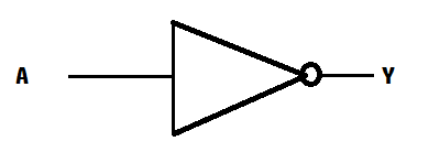
NOT gate is also known as Inverter because it inverts the given input. For example, if the input is 1 then the output is 0 and vice versa. Thus, the first statement is true.
Also, it is well established that it inverts the input, so the second statement is also true and statement 2 is the correct explanation of statement 1. Thus, the correct option is (A).
Additional information:
The (o) present at the end of the NOT gate symbol denotes a signal inversion of the output signal. NOT gates can also be derived from NAND and NOR gates by connecting together ALL their inputs to a common single input signal.
Note:Always remember the NOT gate has only one input and one output signal.It will help you identify the NOT gate in most of the cases because mostly we used to derive NOT gate from the universal gate.
Complete step by step answer:
NOT gate is an electronic circuit that produces an inverted version of the input at its output. It has one input A and one output Y as shown in the figure below
NOT gate is also known as Inverter because it inverts the given input. For example, if the input is 1 then the output is 0 and vice versa. Thus, the first statement is true.
Also, it is well established that it inverts the input, so the second statement is also true and statement 2 is the correct explanation of statement 1. Thus, the correct option is (A).
Additional information:
The (o) present at the end of the NOT gate symbol denotes a signal inversion of the output signal. NOT gates can also be derived from NAND and NOR gates by connecting together ALL their inputs to a common single input signal.
Note:Always remember the NOT gate has only one input and one output signal.It will help you identify the NOT gate in most of the cases because mostly we used to derive NOT gate from the universal gate.
Recently Updated Pages
Explain the structure of megasporangium class 12 biology CBSE

Why is chloroform kept in dark coloured bottles class 12 chemistry CBSE
Derive the balancing condition of a Wheatstone bri class 12 physics CBSE
Draw VI characteristics of a pn junction diode Explain class 12 physics CBSE
Is it possible to carry pride in ones language too class 12 english CBSE
In a population at Hardy Weinberg equilibrium the allele class 12 biology CBSE
Trending doubts
Draw a labelled sketch of the human eye class 12 physics CBSE
Which are the Top 10 Largest Countries of the World?
Draw ray diagrams each showing i myopic eye and ii class 12 physics CBSE
One megawatt is equal to how many units of electri class 12 physics CBSE
Which is the correct genotypic ratio of mendel dihybrid class 12 biology CBSE
Give 10 examples of unisexual and bisexual flowers