


What is rectification? Draw the circuit diagram of a half wave rectifier and explain its working. Show the input ac voltage and output voltage waveforms from the rectifier circuit.
Answer
568.8k+ views
Hint:The use of a rectifier in the power supply aids in changing the power supply from AC to DC. For big electronics, bridge rectifiers are commonly used, where they are able to transform high AC voltage to low DC voltage.
Complete answer:
The rectifier is an electrical system that transforms alternating current ( AC), which regularly reverses direction , to direct current (DC ) , which flows in one direction only. The technique is known as rectification, since it straightens the current direction.
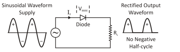
The half-wave rectifier circuit is given in the figure using a semiconductor diode $\left( D \right)$ with a load resistance ${R_L}$ but no smoothing philtre. The diode is related in series with the transformer secondary and the ${R_L}$ load resistance. The primary transformer is attached to the mains of the AC supply.
Following every half period of the input pulse, the ac voltage through the secondary winding alters polarities. The diode is forward biased during the positive half-cycles of the input ac voltage, i.e. when the upper end of the secondary winding is positive with respect to its lower end, and thus conducts current.
If the forward resistance of the diode is believed to be zero (in fact, however, there is a minor resistance), the input voltage is immediately applied to the load resistance RL during the positive half-cycles, making the upper end positive. The output current and output voltage waveforms are of the same shape as that of the AC voltage supply.
The diode is reverse biased during the negative half cycles of the input ac voltage, i.e. when the lower end of the secondary winding is positive with respect to its upper end, and therefore does not work. Thus, the current through and the voltage over the load stays zero during the negative half intervals of the input ac voltage. The reverse current is ignored, being very small in magnitude. Thus, no power is supplied to the load for the negative half-cycles.
Note:By translating an AC voltage signal to a DC voltage signal, a half-wave rectifier diode circuit is constructed. Here, one half of the input signal is allowed by the diode and the other half is rejected. When used for power rectification, the half wave rectifier circuit is used with a transformer if it is to be used for powering equipment in any way. Normally in this application the input alternating waveform is provided via a transformer. This is used to provide the required input voltage.
Complete answer:
The rectifier is an electrical system that transforms alternating current ( AC), which regularly reverses direction , to direct current (DC ) , which flows in one direction only. The technique is known as rectification, since it straightens the current direction.
The half-wave rectifier circuit is given in the figure using a semiconductor diode $\left( D \right)$ with a load resistance ${R_L}$ but no smoothing philtre. The diode is related in series with the transformer secondary and the ${R_L}$ load resistance. The primary transformer is attached to the mains of the AC supply.
Following every half period of the input pulse, the ac voltage through the secondary winding alters polarities. The diode is forward biased during the positive half-cycles of the input ac voltage, i.e. when the upper end of the secondary winding is positive with respect to its lower end, and thus conducts current.
If the forward resistance of the diode is believed to be zero (in fact, however, there is a minor resistance), the input voltage is immediately applied to the load resistance RL during the positive half-cycles, making the upper end positive. The output current and output voltage waveforms are of the same shape as that of the AC voltage supply.
The diode is reverse biased during the negative half cycles of the input ac voltage, i.e. when the lower end of the secondary winding is positive with respect to its upper end, and therefore does not work. Thus, the current through and the voltage over the load stays zero during the negative half intervals of the input ac voltage. The reverse current is ignored, being very small in magnitude. Thus, no power is supplied to the load for the negative half-cycles.
Note:By translating an AC voltage signal to a DC voltage signal, a half-wave rectifier diode circuit is constructed. Here, one half of the input signal is allowed by the diode and the other half is rejected. When used for power rectification, the half wave rectifier circuit is used with a transformer if it is to be used for powering equipment in any way. Normally in this application the input alternating waveform is provided via a transformer. This is used to provide the required input voltage.
Recently Updated Pages
Master Class 12 Economics: Engaging Questions & Answers for Success
Master Class 12 Physics: Engaging Questions & Answers for Success
Master Class 12 English: Engaging Questions & Answers for Success
Master Class 12 Social Science: Engaging Questions & Answers for Success
Master Class 12 Maths: Engaging Questions & Answers for Success
Master Class 12 Business Studies: Engaging Questions & Answers for Success
Trending doubts
Which are the Top 10 Largest Countries of the World?
What are the major means of transport Explain each class 12 social science CBSE
Draw a labelled sketch of the human eye class 12 physics CBSE
Why cannot DNA pass through cell membranes class 12 biology CBSE
Differentiate between insitu conservation and exsitu class 12 biology CBSE
Draw a neat and well labeled diagram of TS of ovary class 12 biology CBSE