


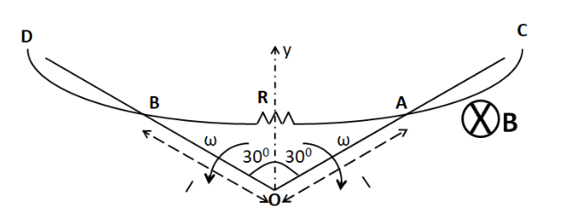
In the figure, there exists a uniform magnetic field $ B $ into the plane of paper. Wire $ CD $ is in the shape of an arc and is fixed. $ OA $ and $ OB $ are the wires rotating with angular velocity $ \omega $ as shown in the figure in the same plane as that of the arc about point $ O $ . If at some instant, $ OA = OB = l $ and each wire makes angle $ \theta = 6 = {30^ \circ } $ with y-axis, then the current through resistance $ R $ is (wire $ OA $ and $ OB $ have no resistance)
(A) $ 0 $
(B) $ \dfrac{{B\omega {l^2}}}{R} $
(C) $ \dfrac{{B\omega {l^2}}}{{2R}} $
(D) $ \dfrac{{B\omega {l^2}}}{{4R}} $
Answer
623.1k+ views
Hint: To solve this question, we have to find out the emf generated in each of the two rods using the motional emf equation. Then, we need to calculate the potential difference across the resistor and hence the current using Ohm’s law.
Formula used: The formulae which are used to solve this question are given by
$e = Blv $ , here $ e $ is the emf induced in a rod of length $ l $ which is moving with a speed of $ v $ in a direction perpendicular to its length in a region of magnetic field $ B $ perpendicular to its plane.
$\vec F = q\left( {\vec v \times \vec B} \right) $ , here $ \vec F $ is the force acting on a charge $ q $ which is moving with a velocity $ \vec v $ in a magnetic field of $ \vec B $ .
Complete step by step solution:
We need to first consider the motion of rod OA. As it moves in the uniform magnetic field which is present into the plane of paper, the Lorentz force acts on each of its free electrons, due to which an emf is generated across its length.
Consider a small element of length $ dr $ on the rod OA, at a distance of $ r $ from the point O, as shown below.
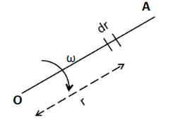
The velocity of this element is
$\Rightarrow v = \omega r $ ………………..(1)
As the rod is moving perpendicular to its length in a magnetic field which is perpendicular to the plane of the rod, so the emf generated across the element is given by
$\Rightarrow de = Bvdr $
From (1)
$\Rightarrow de = B\omega rdr $
For the total emf generated across the whole length of the rod, we integrate the above equation
$\Rightarrow \int\limits_0^e {de} = \int\limits_0^l {B\omega rdr} $
As the magnetic field and the angular velocity are constant, so we have
$\Rightarrow \int\limits_0^e {de} = B\omega \int\limits_0^l {rdr} $
$\Rightarrow \left[ e \right]_0^e = B\omega \left[ {\dfrac{{{r^2}}}{2}} \right]_0^l $
On substituting the limits, we get
$\Rightarrow e = \dfrac{{B\omega {l^2}}}{2} $
From the Lorentz force equation, we have
$\Rightarrow \vec F = q\left( {\vec v \times \vec B} \right) $
For an electron, $ q = - e $ . So we have
$\Rightarrow \vec F = - e\left( {\vec v \times \vec B} \right) $
From the right hand rule, we get the direction of the force on each electron towards the end O of the rod. Hence, the end O of the rod is at a lower potential with respect to the end A, by the amount $ \dfrac{{B\omega {l^2}}}{2} $ .
Similarly, we can show that the end O of the rod OB is at a higher potential than the end B by the same amount. Thus we can replace both the rods OA and OB by the two batteries as shown below.
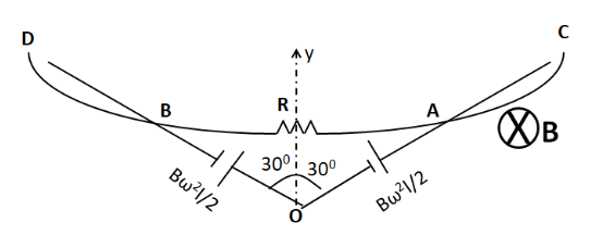
From the above figure, we can see that
$\Rightarrow {V_o} - {V_B} = \dfrac{{B\omega {l^2}}}{2} $ ……………….(2)
Also
$\Rightarrow {V_A} - {V_o} = \dfrac{{B\omega {l^2}}}{2} $ ………………….(3)
Adding (2) and (3), we get
$\Rightarrow {V_o} - {V_B} + {V_A} - {V_o} = \dfrac{{B\omega {l^2}}}{2} + \dfrac{{B\omega {l^2}}}{2} $
On simplifying, we get
$\Rightarrow {V_A} - {V_B} = B\omega {l^2} $
$\Rightarrow {V_{AB}} = B\omega {l^2} $ ………………..(4)
We can see from the above figure that this is the potential across the resistance $ R $ . So the current through the resistance can be given by
$\Rightarrow I = \dfrac{{{V_{AB}}}}{R} $
From (4)
$\Rightarrow I = \dfrac{{B\omega {l^2}}}{R} $
Thus the current through the resistance is equal to $ \dfrac{{B\omega {l^2}}}{R} $ .
Hence the correct answer is option (B).
Note:
We must note that in this question, the values of the angles made by the wires with the y-axis given are useless. They are just given to deviate us from the correct approach. We don’t try to find out the area of the triangle from the value of these angles, as no triangle is formed in the figure. This is because the wire AB is not straight but is in the form of an arc.
Formula used: The formulae which are used to solve this question are given by
$e = Blv $ , here $ e $ is the emf induced in a rod of length $ l $ which is moving with a speed of $ v $ in a direction perpendicular to its length in a region of magnetic field $ B $ perpendicular to its plane.
$\vec F = q\left( {\vec v \times \vec B} \right) $ , here $ \vec F $ is the force acting on a charge $ q $ which is moving with a velocity $ \vec v $ in a magnetic field of $ \vec B $ .
Complete step by step solution:
We need to first consider the motion of rod OA. As it moves in the uniform magnetic field which is present into the plane of paper, the Lorentz force acts on each of its free electrons, due to which an emf is generated across its length.
Consider a small element of length $ dr $ on the rod OA, at a distance of $ r $ from the point O, as shown below.
The velocity of this element is
$\Rightarrow v = \omega r $ ………………..(1)
As the rod is moving perpendicular to its length in a magnetic field which is perpendicular to the plane of the rod, so the emf generated across the element is given by
$\Rightarrow de = Bvdr $
From (1)
$\Rightarrow de = B\omega rdr $
For the total emf generated across the whole length of the rod, we integrate the above equation
$\Rightarrow \int\limits_0^e {de} = \int\limits_0^l {B\omega rdr} $
As the magnetic field and the angular velocity are constant, so we have
$\Rightarrow \int\limits_0^e {de} = B\omega \int\limits_0^l {rdr} $
$\Rightarrow \left[ e \right]_0^e = B\omega \left[ {\dfrac{{{r^2}}}{2}} \right]_0^l $
On substituting the limits, we get
$\Rightarrow e = \dfrac{{B\omega {l^2}}}{2} $
From the Lorentz force equation, we have
$\Rightarrow \vec F = q\left( {\vec v \times \vec B} \right) $
For an electron, $ q = - e $ . So we have
$\Rightarrow \vec F = - e\left( {\vec v \times \vec B} \right) $
From the right hand rule, we get the direction of the force on each electron towards the end O of the rod. Hence, the end O of the rod is at a lower potential with respect to the end A, by the amount $ \dfrac{{B\omega {l^2}}}{2} $ .
Similarly, we can show that the end O of the rod OB is at a higher potential than the end B by the same amount. Thus we can replace both the rods OA and OB by the two batteries as shown below.
From the above figure, we can see that
$\Rightarrow {V_o} - {V_B} = \dfrac{{B\omega {l^2}}}{2} $ ……………….(2)
Also
$\Rightarrow {V_A} - {V_o} = \dfrac{{B\omega {l^2}}}{2} $ ………………….(3)
Adding (2) and (3), we get
$\Rightarrow {V_o} - {V_B} + {V_A} - {V_o} = \dfrac{{B\omega {l^2}}}{2} + \dfrac{{B\omega {l^2}}}{2} $
On simplifying, we get
$\Rightarrow {V_A} - {V_B} = B\omega {l^2} $
$\Rightarrow {V_{AB}} = B\omega {l^2} $ ………………..(4)
We can see from the above figure that this is the potential across the resistance $ R $ . So the current through the resistance can be given by
$\Rightarrow I = \dfrac{{{V_{AB}}}}{R} $
From (4)
$\Rightarrow I = \dfrac{{B\omega {l^2}}}{R} $
Thus the current through the resistance is equal to $ \dfrac{{B\omega {l^2}}}{R} $ .
Hence the correct answer is option (B).
Note:
We must note that in this question, the values of the angles made by the wires with the y-axis given are useless. They are just given to deviate us from the correct approach. We don’t try to find out the area of the triangle from the value of these angles, as no triangle is formed in the figure. This is because the wire AB is not straight but is in the form of an arc.
Recently Updated Pages
Basicity of sulphurous acid and sulphuric acid are
Master Class 12 Economics: Engaging Questions & Answers for Success
Master Class 12 Biology: Engaging Questions & Answers for Success
Master Class 11 English: Engaging Questions & Answers for Success
Master Class 11 Physics: Engaging Questions & Answers for Success
Master Class 11 Computer Science: Engaging Questions & Answers for Success
Trending doubts
Draw a labelled sketch of the human eye class 12 physics CBSE
The chemical formula of tear gas is A CO Cl 2 B C 10 class 12 chemistry CBSE
Draw ray diagrams each showing i myopic eye and ii class 12 physics CBSE
Which are the Top 10 Largest Countries of the World?
Differentiate between homogeneous and heterogeneous class 12 chemistry CBSE
Which is the correct genotypic ratio of mendel dihybrid class 12 biology CBSE