


In the figure is shown a system of four capacitors connected across a 10V battery. Charge that will flow from switch S when it is closed is:
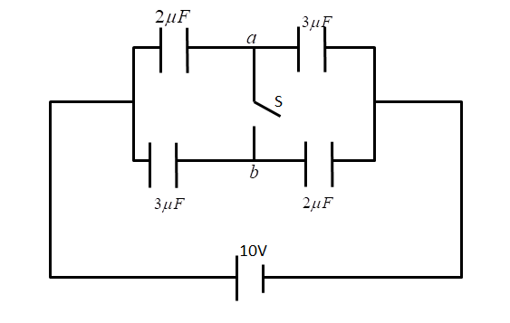
A. Zero
B. $20\mu C$ from a to b
C. $5\mu C$ from b to a
D. $5\mu C$ from a to b
Answer
641.1k+ views
Hint: To solve this problem, we will use the concept of charging and discharging of capacitors and also we know that the capacitor blocks the DC current. We will proceed by solving the series and parallel capacitor circuit for the cases when the switch is on and when the switch is closed.
Formula used- When capacitor are in series, the equivalent capacitance is
$
\dfrac{1}{{{C_{eq}}}} = \dfrac{1}{{{C_1}}} + \dfrac{1}{{{C_2}}} \\
{C_{eq}} = \dfrac{{{C_1}{C_2}}}{{{C_1} + {C_2}}} \\
$
And when capacitors are in parallel, the equivalent capacitance is
${C_{eq}} = {C_1} + {C_2}$
Complete step-by-step answer:
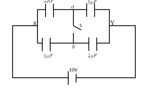
Case 1 When the switch was open, the equivalent capacitance is
For parallel path XaY
$
{C_{aeq}} = \dfrac{{{C_1} \times {C_2}}}{{{C_1} + {C_2}}} \\
{C_{aeq}} = \dfrac{{2 \times 3}}{{2 + 3}} \\
{C_{aeq}} = 1.2\mu F \\
$
Similarly for the other parallel path XbY, the equivalent capacitance is
$
{C_{beq}} = \dfrac{{{C_3} \times {C_4}}}{{{C_3} + {C_4}}} \\
{C_{beq}} = \dfrac{{2 \times 3}}{{2 + 3}} \\
{C_{beq}} = 1.2\mu F \\
$
The net equivalent capacitance is
$
{C_{eq}} = {C_{aeq}} + {C_{beq}} \\
{C_{eq}} = 1.2 + 1.2 \\
{C_{eq}} = 2.4\mu F \\
$
The voltage of the circuit is 10V
Net charge is given by
$
{Q_{net}} = {C_{eq}}V \\
{Q_{net}} = 2.4\mu F \times 10V \\
{Q_{net}} = 24\mu C \\
$
This net charge will distribute among the capacitors as shown in the figure.
$$
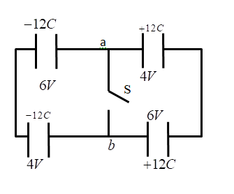
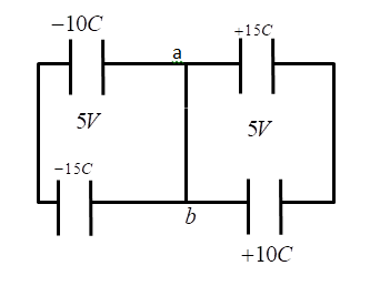
Case 2 When the switch is closed, the charge distribution is shown in the figure below. As the switch is closed the potential at point a and b will be the same.
Let the potential at the positive terminal i.e. at a be V and the potential at the negative terminal of the capacitor 0.
The charge across the capacitor ${C_1} = 2\mu F$ is ${Q_1}$
${Q_1} = \left( {10 - V} \right) \times 2\mu F........\left( 1 \right)$
The charge across the capacitor ${C_2} = 3\mu F$ is ${Q_2}$
${Q_2} = \left( {10 - V} \right) \times 3\mu F........\left( 2 \right)$
The charge across the capacitor ${C_3} = 3\mu F$ is ${Q_3}$
\[{Q_3} = V \times 3\mu F........\left( 3 \right)\]
The charge across the capacitor ${C_2} = 2\mu F$ is ${Q_4}$
${Q_4} = V \times 2\mu F........\left( 4 \right)$
Since, the capacitor ${C_1} = {C_4}{\text{ and }}{{\text{C}}_2} = {C_3}$
Therefore ${Q_1} = {Q_4}{\text{ and }}{{\text{Q}}_2} = {Q_3}$
From equation (1) and equation (4)
$
\left( {10 - V} \right) \times 2 = 2V \\
20 - 2V = 2V \\
4V = 20 \\
V = 5 \\
$
From equation (1) and equation (3)
$
{Q_3} = 5 \times 3 \\
{Q_3} = 15\mu F \\
{Q_1} = \left( {10 - V} \right) \times 2 \\
{Q_1} = \left( {10 - 5} \right) \times 2 \\
{Q_1} = 10\mu F \\
$
Therefore
${Q_1} = {Q_4}{\text{ = 10}}\mu {\text{F and }}{{\text{Q}}_2} = {Q_3} = 15\mu F$
From it is clear that the charge will flow from point b towards point a
And the net charge flow is $5\mu F$
Hence, the correct option is C.
Note- In order to solve these types of problems, remember the relation between charge and voltage and learn how to find the equivalent capacitances. Also when the capacitors are in series, the total capacitance is always less than the minimum of them and if two capacitors are in parallel, then the total capacitance is the sum of them. Remember charge flows from high value to low value.
Formula used- When capacitor are in series, the equivalent capacitance is
$
\dfrac{1}{{{C_{eq}}}} = \dfrac{1}{{{C_1}}} + \dfrac{1}{{{C_2}}} \\
{C_{eq}} = \dfrac{{{C_1}{C_2}}}{{{C_1} + {C_2}}} \\
$
And when capacitors are in parallel, the equivalent capacitance is
${C_{eq}} = {C_1} + {C_2}$
Complete step-by-step answer:
Case 1 When the switch was open, the equivalent capacitance is
For parallel path XaY
$
{C_{aeq}} = \dfrac{{{C_1} \times {C_2}}}{{{C_1} + {C_2}}} \\
{C_{aeq}} = \dfrac{{2 \times 3}}{{2 + 3}} \\
{C_{aeq}} = 1.2\mu F \\
$
Similarly for the other parallel path XbY, the equivalent capacitance is
$
{C_{beq}} = \dfrac{{{C_3} \times {C_4}}}{{{C_3} + {C_4}}} \\
{C_{beq}} = \dfrac{{2 \times 3}}{{2 + 3}} \\
{C_{beq}} = 1.2\mu F \\
$
The net equivalent capacitance is
$
{C_{eq}} = {C_{aeq}} + {C_{beq}} \\
{C_{eq}} = 1.2 + 1.2 \\
{C_{eq}} = 2.4\mu F \\
$
The voltage of the circuit is 10V
Net charge is given by
$
{Q_{net}} = {C_{eq}}V \\
{Q_{net}} = 2.4\mu F \times 10V \\
{Q_{net}} = 24\mu C \\
$
This net charge will distribute among the capacitors as shown in the figure.
$$
Case 2 When the switch is closed, the charge distribution is shown in the figure below. As the switch is closed the potential at point a and b will be the same.
Let the potential at the positive terminal i.e. at a be V and the potential at the negative terminal of the capacitor 0.
The charge across the capacitor ${C_1} = 2\mu F$ is ${Q_1}$
${Q_1} = \left( {10 - V} \right) \times 2\mu F........\left( 1 \right)$
The charge across the capacitor ${C_2} = 3\mu F$ is ${Q_2}$
${Q_2} = \left( {10 - V} \right) \times 3\mu F........\left( 2 \right)$
The charge across the capacitor ${C_3} = 3\mu F$ is ${Q_3}$
\[{Q_3} = V \times 3\mu F........\left( 3 \right)\]
The charge across the capacitor ${C_2} = 2\mu F$ is ${Q_4}$
${Q_4} = V \times 2\mu F........\left( 4 \right)$
Since, the capacitor ${C_1} = {C_4}{\text{ and }}{{\text{C}}_2} = {C_3}$
Therefore ${Q_1} = {Q_4}{\text{ and }}{{\text{Q}}_2} = {Q_3}$
From equation (1) and equation (4)
$
\left( {10 - V} \right) \times 2 = 2V \\
20 - 2V = 2V \\
4V = 20 \\
V = 5 \\
$
From equation (1) and equation (3)
$
{Q_3} = 5 \times 3 \\
{Q_3} = 15\mu F \\
{Q_1} = \left( {10 - V} \right) \times 2 \\
{Q_1} = \left( {10 - 5} \right) \times 2 \\
{Q_1} = 10\mu F \\
$
Therefore
${Q_1} = {Q_4}{\text{ = 10}}\mu {\text{F and }}{{\text{Q}}_2} = {Q_3} = 15\mu F$
From it is clear that the charge will flow from point b towards point a
And the net charge flow is $5\mu F$
Hence, the correct option is C.
Note- In order to solve these types of problems, remember the relation between charge and voltage and learn how to find the equivalent capacitances. Also when the capacitors are in series, the total capacitance is always less than the minimum of them and if two capacitors are in parallel, then the total capacitance is the sum of them. Remember charge flows from high value to low value.
Recently Updated Pages
Master Class 12 Business Studies: Engaging Questions & Answers for Success
Master Class 12 Chemistry: Engaging Questions & Answers for Success
Master Class 12 Biology: Engaging Questions & Answers for Success
Class 12 Question and Answer - Your Ultimate Solutions Guide
Master Class 11 English: Engaging Questions & Answers for Success
Master Class 11 Social Science: Engaging Questions & Answers for Success
Trending doubts
Which are the Top 10 Largest Countries of the World?
Draw a labelled sketch of the human eye class 12 physics CBSE
Differentiate between homogeneous and heterogeneous class 12 chemistry CBSE
Differentiate between Pyramid of energy and pyramid class 12 biology CBSE
Why is the cell called the structural and functional class 12 biology CBSE
Draw the diagram of the pyramid of energy Explain In class 12 biology CBSE