


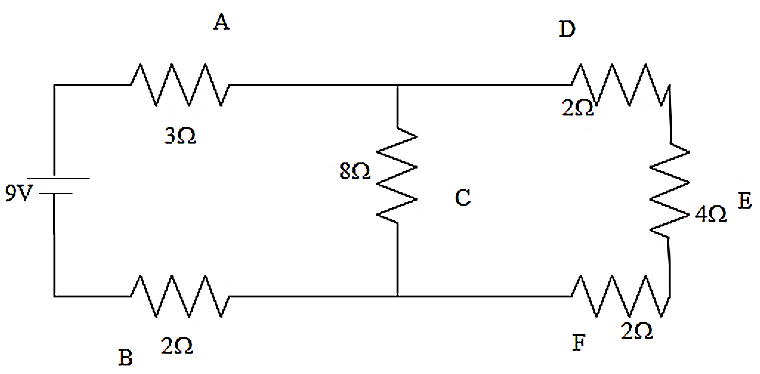
In the electrical circuit as mentioned in given diagram, the current through the $4\Omega $ resistor will be given as,
$\begin{align}
& A.1A \\
& B.0.5A \\
& C.0.25A \\
& D.0.1A \\
\end{align}$
Answer
558.6k+ views
Hint: Analyse the circuit well. The equivalent resistance is to be found first. According to ohm’s law, the potential of the circuit will be the product of the current produced and the resistance of the circuit. Using this relation find the overall current in the circuit. Then find the division of this current in each branch of the circuit. This will help you in answering this question.
Complete answer:
As we look into the diagram we can see that the resistance D, E, F are connected in series. Therefore the total resistance of these three resistances will be given as,
${{R}_{1}}=2+4+2=8\Omega $
Now this effective resistance will be in parallel connection with the resistance C. This can be written as,
$\begin{align}
& \dfrac{1}{{{R}_{2}}}=\dfrac{1}{8}+\dfrac{1}{8}=\dfrac{1}{4} \\
& {{R}_{2}}=4\Omega \\
\end{align}$
Now the circuit will become like this.
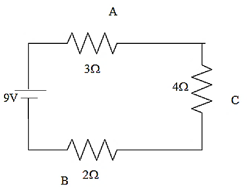
The three resistors in the circuit now are in series connection with each other. Therefore their effective resistance will be the sum of each of the resistance values.
That is we can write that,
${{R}_{eq}}=4+3+2=9\Omega $
Therefore the effective resistance of the circuit has been obtained.
According to Ohm's law, the potential of the circuit will be the product of the current produced and the resistance of the circuit. Therefore we can use it here also. The equation can be shown as,
$V=IR$
The potential used in this circuit has been given as,
$V=9V$
Let us substitute the values in it,
$\begin{align}
& 9=I\times 9 \\
& \Rightarrow I=1A \\
\end{align}$
The value of current in the resistor C will be
${{I}_{C}}=1A$
This current will be divided equally in both the branches as they are connected in parallel. Therefore each branch will be having a total current of,
${{I}_{DEF}}=0.5A$
As the resistors D, E, F are in series the current will be the same in all the resistors. Therefore the current in $4\Omega $ resistor will be $0.5A$.
The answer has been given as option B.
Note:
When the resistors are in series connection, then their equivalent resistance will be the sum of the individual resistance. When the resistors are connected in parallel, the reciprocal of the effective resistance of the circuit will be the sum of the reciprocal of each of the resistances.
Complete answer:
As we look into the diagram we can see that the resistance D, E, F are connected in series. Therefore the total resistance of these three resistances will be given as,
${{R}_{1}}=2+4+2=8\Omega $
Now this effective resistance will be in parallel connection with the resistance C. This can be written as,
$\begin{align}
& \dfrac{1}{{{R}_{2}}}=\dfrac{1}{8}+\dfrac{1}{8}=\dfrac{1}{4} \\
& {{R}_{2}}=4\Omega \\
\end{align}$
Now the circuit will become like this.
The three resistors in the circuit now are in series connection with each other. Therefore their effective resistance will be the sum of each of the resistance values.
That is we can write that,
${{R}_{eq}}=4+3+2=9\Omega $
Therefore the effective resistance of the circuit has been obtained.
According to Ohm's law, the potential of the circuit will be the product of the current produced and the resistance of the circuit. Therefore we can use it here also. The equation can be shown as,
$V=IR$
The potential used in this circuit has been given as,
$V=9V$
Let us substitute the values in it,
$\begin{align}
& 9=I\times 9 \\
& \Rightarrow I=1A \\
\end{align}$
The value of current in the resistor C will be
${{I}_{C}}=1A$
This current will be divided equally in both the branches as they are connected in parallel. Therefore each branch will be having a total current of,
${{I}_{DEF}}=0.5A$
As the resistors D, E, F are in series the current will be the same in all the resistors. Therefore the current in $4\Omega $ resistor will be $0.5A$.
The answer has been given as option B.
Note:
When the resistors are in series connection, then their equivalent resistance will be the sum of the individual resistance. When the resistors are connected in parallel, the reciprocal of the effective resistance of the circuit will be the sum of the reciprocal of each of the resistances.
Recently Updated Pages
Master Class 12 Economics: Engaging Questions & Answers for Success
Master Class 12 Physics: Engaging Questions & Answers for Success
Master Class 12 English: Engaging Questions & Answers for Success
Master Class 12 Social Science: Engaging Questions & Answers for Success
Master Class 12 Maths: Engaging Questions & Answers for Success
Master Class 12 Business Studies: Engaging Questions & Answers for Success
Trending doubts
Which are the Top 10 Largest Countries of the World?
What are the major means of transport Explain each class 12 social science CBSE
Draw a labelled sketch of the human eye class 12 physics CBSE
Why cannot DNA pass through cell membranes class 12 biology CBSE
Differentiate between insitu conservation and exsitu class 12 biology CBSE
Draw a neat and well labeled diagram of TS of ovary class 12 biology CBSE