


In the circuit shown, the total current supplied by the battery is
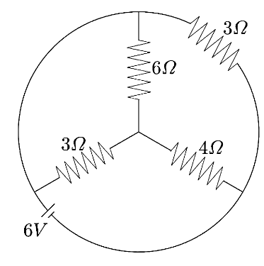
A. $1A\;$
B. $2A\;$
C. $3A\;$
D. $6A\;$
Answer
542.4k+ views
Hint: We can find the total current supplied by the battery using Ohm’s Law which states that voltage of a battery is the product of the current supplied and the total resistance. To find the total resistance, we need to rearrange the given circuit to understand the series and parallel connections.
Formula used:
Series connection of resistors ${{R}_{eq}}={{R}_{1}}+{{R}_{2}}+...+{{R}_{n}}$
Parallel connection of resistors $\dfrac{1}{{{R}_{eq}}}=\dfrac{1}{{{R}_{1}}}+\dfrac{1}{{{R}_{2}}}+...+\dfrac{1}{{{R}_{n}}}$
Ohm’s Law $V=IR$
Complete step by step answer:
Let us note down the given data,
${{R}_{1}}=3\Omega $ , ${{R}_{2}}=6\Omega $ , ${{R}_{3}}=4\Omega $ , ${{R}_{4}}=3\Omega $ , and $V=6V$
Now, let us name the nodes to understand the series and parallel connections of resistors as shown below,
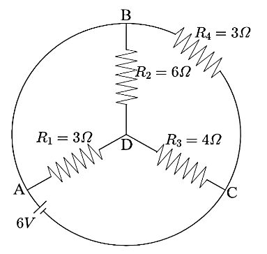
Now, from the figure above, we can see that between the points $A$ and $B$ there is a simple wire. This means that the potential at points $A$ and $B$ is the same. Hence, they can be considered as the same points.
Thus, we can see that the resistors $R_1$ and $R_2$ are connected between the same points and hence, they are said to be connected in parallel connection. Now, the combination of $R_1$ and $R_2$ is directly connected to resistance $R_3$ . Hence, this is a serious connection.
Now, the combination of $R_1$ , $R_2$ , and $R_3$ is connected between the points $A$ and $C$ and so is the resistance $R_4$ . Hence, this is a parallel connection. Hence, the above shown circuit can be redesigned as below,
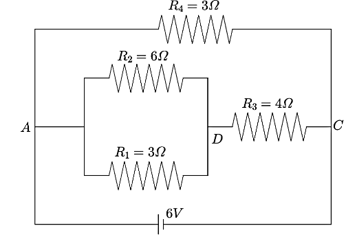
Now, we can see from the above figure that the resistance $R_1$ and $R_2$ are in parallel connection and the equivalent reaction can be calculated as,
$\dfrac{1}{R'}=\dfrac{1}{{{R}_{1}}}+\dfrac{1}{{{R}_{2}}}$
Substituting the given values,
$\dfrac{1}{R'}=\dfrac{1}{3\Omega }+\dfrac{1}{6\Omega }$
$\Rightarrow \dfrac{1}{R'}=\dfrac{3}{6\Omega }$
Taking the reciprocal on both sides,
$\Rightarrow R'=\dfrac{6}{3}\Omega $
$\Rightarrow R'=2\Omega $
Now, the circuit can be drawn as shown below,
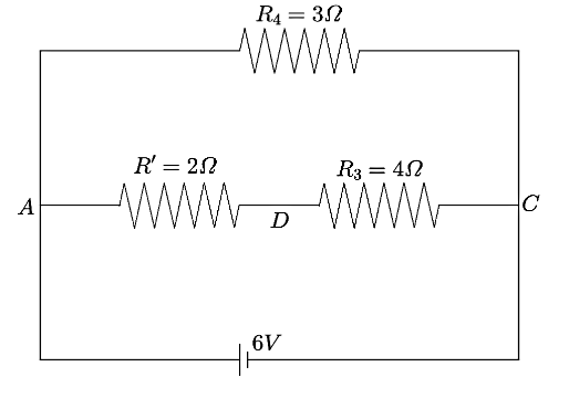
Now, the resistances $R'\;$ and $R_3$ are connected in series. Hence, the equivalent resistance can be calculated as
$R''=R'+{{R}_{3}}$
Substituting the given values,
$\Rightarrow R''=2\Omega +4\Omega $
$\Rightarrow R''=6\Omega $
Now, the circuit can be redrawn as shown below,
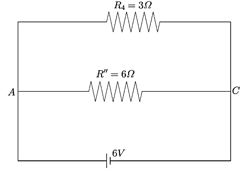
Now, the resistances $R''\;$ and $R_4$ are connected in parallel connection. Hence, the equivalent resistance can be calculated as
$\dfrac{1}{{{R}_{eq}}}=\dfrac{1}{R''}+\dfrac{1}{{{R}_{4}}}$
Substituting the given values,
$\dfrac{1}{{{R}_{eq}}}=\dfrac{1}{6\Omega }+\dfrac{1}{3\Omega }$
$\Rightarrow \dfrac{1}{{{{R}}_{eq}}}=\dfrac{3}{6\Omega }$
Taking the reciprocal on both sides,
$\Rightarrow {{R}_{eq}}=\dfrac{6}{3}\Omega $
$\Rightarrow {{R}_{eq}}=2\Omega $
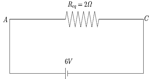
This is the total resistance of the circuit. Now, the total current can be calculated using the Ohm’s Law
$V=IR$
Substituting the given values,
$\Rightarrow 6V=I(2\Omega )$
$\therefore I=3A$
Hence, the correct answer is option C.
Note: We should note that in this type of problem, we should always start by naming the junctions in the circuit. While naming, if there is no other component other than a simple wire between the two points, then those two points are considered to be the same. We should remember that resistors are said to be in parallel when they are connected between the same two points, and they are said to be in series when they are connected in a line.
Formula used:
Series connection of resistors ${{R}_{eq}}={{R}_{1}}+{{R}_{2}}+...+{{R}_{n}}$
Parallel connection of resistors $\dfrac{1}{{{R}_{eq}}}=\dfrac{1}{{{R}_{1}}}+\dfrac{1}{{{R}_{2}}}+...+\dfrac{1}{{{R}_{n}}}$
Ohm’s Law $V=IR$
Complete step by step answer:
Let us note down the given data,
${{R}_{1}}=3\Omega $ , ${{R}_{2}}=6\Omega $ , ${{R}_{3}}=4\Omega $ , ${{R}_{4}}=3\Omega $ , and $V=6V$
Now, let us name the nodes to understand the series and parallel connections of resistors as shown below,
Now, from the figure above, we can see that between the points $A$ and $B$ there is a simple wire. This means that the potential at points $A$ and $B$ is the same. Hence, they can be considered as the same points.
Thus, we can see that the resistors $R_1$ and $R_2$ are connected between the same points and hence, they are said to be connected in parallel connection. Now, the combination of $R_1$ and $R_2$ is directly connected to resistance $R_3$ . Hence, this is a serious connection.
Now, the combination of $R_1$ , $R_2$ , and $R_3$ is connected between the points $A$ and $C$ and so is the resistance $R_4$ . Hence, this is a parallel connection. Hence, the above shown circuit can be redesigned as below,
Now, we can see from the above figure that the resistance $R_1$ and $R_2$ are in parallel connection and the equivalent reaction can be calculated as,
$\dfrac{1}{R'}=\dfrac{1}{{{R}_{1}}}+\dfrac{1}{{{R}_{2}}}$
Substituting the given values,
$\dfrac{1}{R'}=\dfrac{1}{3\Omega }+\dfrac{1}{6\Omega }$
$\Rightarrow \dfrac{1}{R'}=\dfrac{3}{6\Omega }$
Taking the reciprocal on both sides,
$\Rightarrow R'=\dfrac{6}{3}\Omega $
$\Rightarrow R'=2\Omega $
Now, the circuit can be drawn as shown below,
Now, the resistances $R'\;$ and $R_3$ are connected in series. Hence, the equivalent resistance can be calculated as
$R''=R'+{{R}_{3}}$
Substituting the given values,
$\Rightarrow R''=2\Omega +4\Omega $
$\Rightarrow R''=6\Omega $
Now, the circuit can be redrawn as shown below,
Now, the resistances $R''\;$ and $R_4$ are connected in parallel connection. Hence, the equivalent resistance can be calculated as
$\dfrac{1}{{{R}_{eq}}}=\dfrac{1}{R''}+\dfrac{1}{{{R}_{4}}}$
Substituting the given values,
$\dfrac{1}{{{R}_{eq}}}=\dfrac{1}{6\Omega }+\dfrac{1}{3\Omega }$
$\Rightarrow \dfrac{1}{{{{R}}_{eq}}}=\dfrac{3}{6\Omega }$
Taking the reciprocal on both sides,
$\Rightarrow {{R}_{eq}}=\dfrac{6}{3}\Omega $
$\Rightarrow {{R}_{eq}}=2\Omega $
This is the total resistance of the circuit. Now, the total current can be calculated using the Ohm’s Law
$V=IR$
Substituting the given values,
$\Rightarrow 6V=I(2\Omega )$
$\therefore I=3A$
Hence, the correct answer is option C.
Note: We should note that in this type of problem, we should always start by naming the junctions in the circuit. While naming, if there is no other component other than a simple wire between the two points, then those two points are considered to be the same. We should remember that resistors are said to be in parallel when they are connected between the same two points, and they are said to be in series when they are connected in a line.
Recently Updated Pages
Master Class 12 Business Studies: Engaging Questions & Answers for Success
Master Class 12 Biology: Engaging Questions & Answers for Success
Master Class 12 Chemistry: Engaging Questions & Answers for Success
Class 12 Question and Answer - Your Ultimate Solutions Guide
Master Class 11 Social Science: Engaging Questions & Answers for Success
Master Class 11 English: Engaging Questions & Answers for Success
Trending doubts
Which are the Top 10 Largest Countries of the World?
Draw a labelled sketch of the human eye class 12 physics CBSE
Name the crygenes that control cotton bollworm and class 12 biology CBSE
Differentiate between homogeneous and heterogeneous class 12 chemistry CBSE
Ribosomal RNA is actively synthesised in A Nucleoplasm class 12 biology CBSE
How many molecules of ATP and NADPH are required information class 12 biology CBSE