


In the circuit shown, the diode is ideal. The potential of A is higher than the potential of B. If the switch S is (i) closed, (ii) open, the equivalent resistance between A and B is:
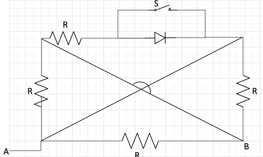
$\text{A.}\ R,R$
$\text{B.}\ \dfrac{R}{2},\dfrac{R}{2}$
$\text{C.}\ \dfrac{R}{3},\dfrac{R}{4}$
$\text{D.}\ \dfrac{R}{4},\dfrac{R}{3}$
Answer
601.2k+ views
Hint: p-n junction is an active element of the circuit, which is used where we want the flow of current in one direction and not in both. It is called a p-n junction because it is built using a p-type and a n-type semiconductor. When this diode is forward biased, only in that case it allows the current to flow through it. Being forward biased means that it has its flat end at higher potential and pointed end at lower potential.
Formula used:
$\dfrac1R_{net} = \dfrac1R_1 + \dfrac1R_2 + \dfrac1R_3 +. . .$
Complete answer:
In the condition of the switch to be closed, all current will flow through the diode as the switch branch will be discontinuous and the diode is forward biased ($V_A > V_B$). In that case we can redraw the circuit as:
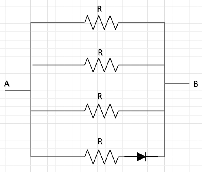
Hence, the equivalent resistance between A and B will be the combination of four resistors in parallel.
Thus using$\dfrac1R_{net} = \dfrac1R_1 + \dfrac1R_2 + \dfrac1R_3 +. . .$
$\dfrac{1}{R_{net}} = \dfrac1R +\dfrac1R +\dfrac1R +\dfrac1R$
$R_{net} = \dfrac{R}{4}$
Now, in case 2, after opening the switch, the diode and resistor will get short circuited and hence won’t contribute for the net resistance of the circuit. Hence the circuit can be redrawn as:
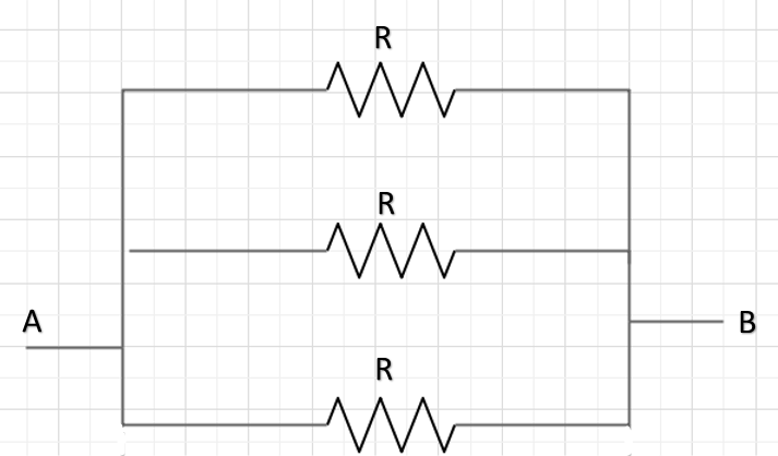
Now, in this case, the net resistance will be:
$\dfrac1R_{net} = \dfrac1R_1 + \dfrac1R_2 + \dfrac1R_3 +. . .$
$\dfrac{1}{R_{net}} = \dfrac1R +\dfrac1R +\dfrac1R$
$R_{net} = \dfrac R3$
So, the correct answer is “Option D”.
Note:
An ideal diode is the one which provides no resistance to the flow of current. Since in this question, we are given an ideal diode, thus it won’t contribute to the total resistance. Also, this type of question could be easily solved by redrawing the circuit and then seeing between A and B, how many resistors are present. And since they all are present between two common points, hence the potential difference between them all will be the same and hence said to be in parallel.
Formula used:
$\dfrac1R_{net} = \dfrac1R_1 + \dfrac1R_2 + \dfrac1R_3 +. . .$
Complete answer:
In the condition of the switch to be closed, all current will flow through the diode as the switch branch will be discontinuous and the diode is forward biased ($V_A > V_B$). In that case we can redraw the circuit as:
Hence, the equivalent resistance between A and B will be the combination of four resistors in parallel.
Thus using$\dfrac1R_{net} = \dfrac1R_1 + \dfrac1R_2 + \dfrac1R_3 +. . .$
$\dfrac{1}{R_{net}} = \dfrac1R +\dfrac1R +\dfrac1R +\dfrac1R$
$R_{net} = \dfrac{R}{4}$
Now, in case 2, after opening the switch, the diode and resistor will get short circuited and hence won’t contribute for the net resistance of the circuit. Hence the circuit can be redrawn as:
Now, in this case, the net resistance will be:
$\dfrac1R_{net} = \dfrac1R_1 + \dfrac1R_2 + \dfrac1R_3 +. . .$
$\dfrac{1}{R_{net}} = \dfrac1R +\dfrac1R +\dfrac1R$
$R_{net} = \dfrac R3$
So, the correct answer is “Option D”.
Note:
An ideal diode is the one which provides no resistance to the flow of current. Since in this question, we are given an ideal diode, thus it won’t contribute to the total resistance. Also, this type of question could be easily solved by redrawing the circuit and then seeing between A and B, how many resistors are present. And since they all are present between two common points, hence the potential difference between them all will be the same and hence said to be in parallel.
Recently Updated Pages
Three beakers labelled as A B and C each containing 25 mL of water were taken A small amount of NaOH anhydrous CuSO4 and NaCl were added to the beakers A B and C respectively It was observed that there was an increase in the temperature of the solutions contained in beakers A and B whereas in case of beaker C the temperature of the solution falls Which one of the following statements isarecorrect i In beakers A and B exothermic process has occurred ii In beakers A and B endothermic process has occurred iii In beaker C exothermic process has occurred iv In beaker C endothermic process has occurred
Master Class 12 Social Science: Engaging Questions & Answers for Success
Master Class 12 Physics: Engaging Questions & Answers for Success
Master Class 12 Maths: Engaging Questions & Answers for Success
Master Class 12 Economics: Engaging Questions & Answers for Success
Master Class 12 Chemistry: Engaging Questions & Answers for Success
Three beakers labelled as A B and C each containing 25 mL of water were taken A small amount of NaOH anhydrous CuSO4 and NaCl were added to the beakers A B and C respectively It was observed that there was an increase in the temperature of the solutions contained in beakers A and B whereas in case of beaker C the temperature of the solution falls Which one of the following statements isarecorrect i In beakers A and B exothermic process has occurred ii In beakers A and B endothermic process has occurred iii In beaker C exothermic process has occurred iv In beaker C endothermic process has occurred
Master Class 12 Social Science: Engaging Questions & Answers for Success
Master Class 12 Physics: Engaging Questions & Answers for Success
Trending doubts
Which are the Top 10 Largest Countries of the World?
Draw a labelled sketch of the human eye class 12 physics CBSE
Differentiate between homogeneous and heterogeneous class 12 chemistry CBSE
What are the major means of transport Explain each class 12 social science CBSE
Sulphuric acid is known as the king of acids State class 12 chemistry CBSE
Why should a magnesium ribbon be cleaned before burning class 12 chemistry CBSE