


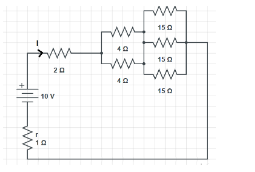
In the Circuit shown in figure, the current \[I\] has a value equal to
\[\begin{align}
& A.IA \\
& B.2A \\
& C.4A \\
& D.3.5A \\
\end{align}\]
Answer
584.4k+ views
Hint: When we see these types of circuit try to find out which resistor is connected in series and which is connected in parallel combination. This will simplify the circuit and we are able to calculate net resistance and therefore the required current. Net Resistance in series \[{{R}_{series}}={{R}_{1}}+{{R}_{2}}+{{R}_{3}}+.....+{{R}_{n}}\] and Net Resistance and parallel \[\dfrac{1}{{{R}_{parallel}}}=\dfrac{1}{{{R}_{1}}}+\dfrac{1}{{{R}_{2}}}+\dfrac{1}{{{R}_{3}}}....\dfrac{1}{{{R}_{n}}}\].
Formula Used:
\[V=IR\]
This is known as Ohm’s Law. Where:
\[V=\]Potential Difference across the circuit
\[I=\] Electric current in the circuit
\[R=\]Resistance in the circuit
And we use,
Resistors connected in series, the net resistance:
\[{{R}_{series}}={{R}_{1}}+{{R}_{2}}+{{R}_{3}}+.....+{{R}_{n}}\]
Resistors connected in parallel, the net resistance:
\[\dfrac{1}{{{R}_{parallel}}}=\dfrac{1}{{{R}_{1}}}+\dfrac{1}{{{R}_{2}}}+\dfrac{1}{{{R}_{3}}}....\dfrac{1}{{{R}_{n}}}\]
Complete step by step answer:
Here three \[15\Omega \] and two \[4\Omega \] resistors are connected in parallel.
For parallel the resultant resistance is:
\[\dfrac{1}{{{R}_{parallel}}}=\dfrac{1}{{{R}_{1}}}+\dfrac{1}{{{R}_{2}}}+\dfrac{1}{{{R}_{3}}}....\dfrac{1}{{{R}_{n}}}\]
And for \[n\] number of resistance connected in parallel
\[{{R}_{parallel}}=\dfrac{R}{n}\]
\[\begin{align}
& {{R}^{'}}_{parallel}=\dfrac{15}{3} \\
& {{R}^{'}}_{parallel}=5\Omega \\
\end{align}\]
\[\begin{align}
& {{R}^{''}}_{parallel}=\dfrac{4}{2} \\
& {{R}^{''}}_{parallel}=2\Omega \\
\end{align}\]
Now, \[R=2\Omega \], \[{{R}^{''}}_{parallel}=2\Omega \], \[{{R}^{'}}_{parallel}=5\Omega \] and internal resistance \[r\] are connected in series. We know that:
\[{{R}_{series}}={{R}_{1}}+{{R}_{2}}+{{R}_{3}}+.....+{{R}_{n}}\]
\[\begin{align}
& {{R}_{series}}={{R}_{1}}+{{R}_{2}}+{{R}_{3}}+r \\
& {{R}_{series}}=2\Omega +2\Omega +5\Omega +1\Omega \\
& {{R}_{series}}=10\Omega \\
\end{align}\]
Also,
\[V=IR\]
\[\begin{align}
& I=\dfrac{\varepsilon }{{{R}_{net}}} \\
& I=\dfrac{10}{10} \\
& I=1A \\
\end{align}\]
Hence, the correct answer is option A.
Additional Information:
Resistance: Resistance is the obstruction in the path of electric current. Or it opposes the current to flow in the circuit.
EMF: EMF or electromotive force, it is not a force. EMF of the cell is the amount of work done in moving the unit test charge from one point of circuit to other point (i.e. throughout the circuit).
Or the EMF is the potential difference between the electrodes of a cell in an open circuit (i.e. when no current is drawn from the cell).
Current: Current is defined as the rate of flow of electric charge through any cross section of the conductor. Current flows from positive to negative direction or opposite to the flow of electrons. It is a scalar quantity.
Internal Resistance: Resistance offered by the electrolyte inside the cell in flow of electric current is called internal resistance of the cell. It is denoted by \[r\].
Note: When resistors are connected in series, current is the same and potential difference is different along each resistor.
When resistors are connected in parallel, potential difference will be the same and current is different along each resistor.
Recently Updated Pages
Master Class 12 Economics: Engaging Questions & Answers for Success
Master Class 12 Physics: Engaging Questions & Answers for Success
Master Class 12 English: Engaging Questions & Answers for Success
Master Class 12 Social Science: Engaging Questions & Answers for Success
Master Class 12 Maths: Engaging Questions & Answers for Success
Master Class 12 Business Studies: Engaging Questions & Answers for Success
Trending doubts
Which are the Top 10 Largest Countries of the World?
What are the major means of transport Explain each class 12 social science CBSE
Draw a labelled sketch of the human eye class 12 physics CBSE
Why cannot DNA pass through cell membranes class 12 biology CBSE
Differentiate between insitu conservation and exsitu class 12 biology CBSE
Draw a neat and well labeled diagram of TS of ovary class 12 biology CBSE