


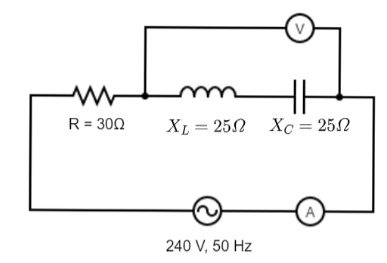
In the circuit shown below, neglecting the source resistance, the voltmeter and ammeter reading will respectively be
A. $0\,V\,,\,8A$
B. $150\,V\,,\,8A$
C. $150\,V\,,\,3A$
D. $0\,V\,,\,3A$
Answer
496.8k+ views
Hint:In this question, we are given individual impedances of all the elements present in the circuit. We shall first calculate the net impedance which is nothing but the sum of individual impedances. Then we shall find the current in the circuit by substituting values in the formula $I = \dfrac{V}{Z}$ where V and Z are both known. This will give us the ammeter reading. Next, we shall calculate the voltage drop across the resistor and use Kirchhoff’s voltage law to determine the voltage drop across the combined series system of the capacitor and the inductor. This will give us the voltmeter reading.
Complete step by step answer:
On analyzing the circuit we have, the source voltage is $V = 240\,V$. The impedance of the resistor is $30\,\Omega $ , while it is $25\,\Omega $ for both the inductor and capacitor.
The net impedance in a series RLC circuit is given by,
$Z = \sqrt {{R^2} + {{({X_L} - {X_C})}^2}} $
Substituting the values in the formula, we get
$Z = \sqrt {{{30}^2} + {{(25 - 25)}^2}} $
Further solving this we get,
$Z = \sqrt {{{30}^2}} $
$ \Rightarrow Z = 30\,\Omega $
So, the net current flowing through the circuit is $I = \dfrac{V}{Z}$.
Substituting the value, we get
$I = \dfrac{{240}}{{30}}$
$ \Rightarrow I = 8\,A$
So, 8 A current flows through the given circuit.
Hence, the reading of the ammeter will be 8 A.
The voltage drop across the resistor is given by ${V_R} = {I_R}R$
Since this is a series RLC circuit, the current flowing through the resistor will be the same as the current flowing through the resistor.
Hence, we can say that $I = {I_R} = 8\,A$
Substituting in the equation we get,
${V_R} = 8 \times 30$
$\Rightarrow {V_R} = 240\,V\,\,\,\,\,\,\,\,\,\,\,\,\,.........(1)$
Now applying Kirchhoff’s Voltage law in the given circuit which states that the sum of voltage drops across all elements in a closed loop is zero.
Hence, we can say that ${V_R} + {V_L} + {V_C} + {V_S} = 0$
Now here we shall assume the direction of the loop to be clockwise. So, the equation becomes $240 + {V_L} + {V_C} - 240 = 0$
$\therefore {V_L} + {V_C} = 0$
This means that the voltage drop across the combined series system of the capacitor and the inductor is zero.
Hence, the reading of the voltmeter will be 0 V.
Note:We can use another approach in this question. When the impedances of the capacitor and inductor are the same, then it is called a resonant circuit. When the circuit is in resonance, there is no voltage drop across the reactive elements. Hence, the voltmeter reading had to be zero anyways. To find out the current flowing in the circuit, we simply would have used the same formula as used above. This would give the ammeter reading.
Recently Updated Pages
Master Class 12 Economics: Engaging Questions & Answers for Success
Master Class 12 Physics: Engaging Questions & Answers for Success
Master Class 12 English: Engaging Questions & Answers for Success
Master Class 12 Social Science: Engaging Questions & Answers for Success
Master Class 12 Maths: Engaging Questions & Answers for Success
Master Class 12 Business Studies: Engaging Questions & Answers for Success
Trending doubts
Which are the Top 10 Largest Countries of the World?
What are the major means of transport Explain each class 12 social science CBSE
Draw a labelled sketch of the human eye class 12 physics CBSE
Why cannot DNA pass through cell membranes class 12 biology CBSE
Differentiate between insitu conservation and exsitu class 12 biology CBSE
Draw a neat and well labeled diagram of TS of ovary class 12 biology CBSE