


In common emitter circuit, current gain is
(A) Zero
(B) Same as in other configuration
(C) Lowest
(D) Highest
Answer
544.8k+ views
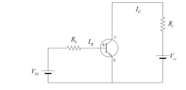
Hint : Hint-Common emitter configuration is one of the important transistor circuit configurations in which the emitter terminal of a transistor is common for both input and output circuit.
Input circuit-The transistor circuit in which input characteristics is drawn between base and emitter terminals.
Output circuit-The transistor circuit in which input characteristics is drawn between collector and emitter terminals.
Current gain: It is the ratio of change in output current divided by change in input current.
For common CE (Common Emitter) configuration, it is the ratio of change in collector current divided by change in base current and denoted by the symbol $\beta $
Complete step-by-step answer-
The common emitter configuration produces the highest current and power gain of all three transistor configurations. The main reason behind that is the input impedance of common emitter configuration is very low as it is connected in forward biased PN junction while the output impedance is high as it is connected in reversed biased PN junction while the output impedance is high. This results in small change in the value of output current and larger in input current.
The current gain in common emitter configuration is given as:
$\beta = \dfrac{{\Delta {I_c}}}{{\Delta {I_b}}}$
Where $\beta $ is the current gain, $\Delta {I_c}$ is the change in collector current and $\Delta {I_b}$is the change in base current.
As $\Delta {I_c} > \Delta {I_b}$ , we have –
$\beta = \dfrac{{\Delta {I_c}}}{{\Delta {I_b}}} > 1$
Hence, we can say that the value of $\beta = \dfrac{{\Delta {I_c}}}{{\Delta {I_b}}}$ will be greater than 1 in common emitter configuration.
Hence, the correct option is Option D.
Note: Basically, there are three types of circuit connections (configurations) for operating transistors.
Common-base (CB)
Common-emitter (CE)
Common-collector (CC)
The term ‘common’ is used to denote the electrode which is common to both input and output circuits. The common electrode is generally grounded; therefore, these modes of operation are frequently referred to ground-base, ground-collector and ground-emitter configurations.
Recently Updated Pages
Master Class 12 Economics: Engaging Questions & Answers for Success
Master Class 12 Physics: Engaging Questions & Answers for Success
Master Class 12 English: Engaging Questions & Answers for Success
Master Class 12 Social Science: Engaging Questions & Answers for Success
Master Class 12 Maths: Engaging Questions & Answers for Success
Master Class 12 Business Studies: Engaging Questions & Answers for Success
Trending doubts
Which are the Top 10 Largest Countries of the World?
What are the major means of transport Explain each class 12 social science CBSE
Draw a labelled sketch of the human eye class 12 physics CBSE
Why cannot DNA pass through cell membranes class 12 biology CBSE
Differentiate between insitu conservation and exsitu class 12 biology CBSE
Draw a neat and well labeled diagram of TS of ovary class 12 biology CBSE