


In a Wheatstone bridge, the four resistance arms of the bridge are $ AB = 2\Omega $ , $ BC = 3\Omega $ , $ CD = 4\Omega $ , and $ DA = 1\Omega $ . A cell of $ emf = 2V $ and negligible internal resistance is connected across $ AC $ and a galvanometer of resistance $ 10\Omega $ is connected between B and D. Find the current through the galvanometer.
Answer
561k+ views
Hint: We draw the diagram of the Wheatstone bridge with 4 resistors keeping in mind the connections. We derive these equations for each closed loop and equate these to zero. Then we apply Cramer’s rule.
Complete step by step answer:
It has been given that, in a Wheatstone bridge, the four resistance arms of the bridge are $ AB = 2\Omega $ , $ BC = 3\Omega $ , $ CD = 4\Omega $ and $ DA = 1\Omega $ . A cell of $ emf = 2V $ and negligible internal resistance is connected across $ AC $ and a galvanometer of resistance $ 10\Omega $ is connected between B and D.
In this case, the diagram would look something like this.
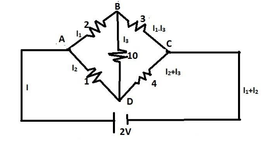
The current flow in this circuit will be as follows:
In closed loop ADBA,
$ 2{I_1} - 1{I_2} + 10{I_3} = 0 $
In closed loop DBCD,
$ 3\left( {{I_1} - {I_3}} \right) - 4\left( {{I_2} + {I_3}} \right) - 10{I_3} = 0 $
$ \Rightarrow 3{I_1} - - 4{I_2} - 17{I_3} = 0 $
In closed loop ADCEA, where point E is the point in the circuit where the cell of emf 2V is connected.
$ 1{I_2} + 4\left( {{I_2} + {I_3}} \right) - 2 = 0 $
$ \Rightarrow 6{I_2} + 4{I_3} - 2 = 0 $
We apply Cramer’s rule to these equations.
Cramer's rule is an explicit formula for the solution of a system of linear equations with as many equations as unknowns, valid whenever the system has a unique solution. It expresses the solution in terms of the determinants of the (square) coefficient matrix and of matrices obtained from it by replacing one column by the column vector of right-hand-sides of the equations.
Coefficient of matrix determinant:
$ I = \left( {\begin{array}{*{20}{c}}
2&{ - 1}&{10} \\
3&{ - 4}&{ - 17} \\
0&6&4
\end{array}} \right) $
Simplifying this matrix, we get,
$ I = 2\left( { - 16 + 102} \right) + 1\left( {12 - 0} \right) - 10\left( {18} \right) $
$ \Rightarrow I = 172 + 12 - 180 = 4A $
Answer column = $ \left( \begin{gathered}
0 \\
0 \\
2 \\
\end{gathered} \right) $ .
$ {I_x} = \left( {\begin{array}{*{20}{c}}
0&{ - 1}&{10} \\
0&{ - 4}&{ - 17} \\
2&6&4
\end{array}} \right) $
$ \Rightarrow {I_x} = 2\left( {17 + 40} \right) = 2 \times 57 = 114A $
$ {I_y} = \left( {\begin{array}{*{20}{c}}
2&0&{10} \\
3&0&{ - 17} \\
0&2&4
\end{array}} \right) $
$ \Rightarrow {I_y} = 0 $
$ {I_z} = \left( {\begin{array}{*{20}{c}}
2&{ - 1}&0 \\
3&{ - 4}&0 \\
0&6&2
\end{array}} \right) $
$ \Rightarrow {I_z} = 2\left( { - 8 + 3} \right) = - 10 $
Thus, current through the galvanometer, $ {I_3} = \dfrac{{{I_z}}}{I} = \dfrac{{10}}{4} = 2.5A $ .
Note:
The Wheatstone Bridge was originally developed by Charles Wheatstone to measure unknown resistance values and as a means of calibrating measuring instruments, voltmeters, ammeters, etc, by the use of a long resistive slide wire.
The Wheatstone Bridge circuit is nothing more than two simple series-parallel arrangements of resistances connected between a voltage supply terminal and ground producing zero voltage difference between the two parallel branches when balanced. A Wheatstone bridge circuit has two input terminals and two output terminals consisting of four resistors configured in a diamond-like arrangement as shown in the figure above.
Complete step by step answer:
It has been given that, in a Wheatstone bridge, the four resistance arms of the bridge are $ AB = 2\Omega $ , $ BC = 3\Omega $ , $ CD = 4\Omega $ and $ DA = 1\Omega $ . A cell of $ emf = 2V $ and negligible internal resistance is connected across $ AC $ and a galvanometer of resistance $ 10\Omega $ is connected between B and D.
In this case, the diagram would look something like this.
The current flow in this circuit will be as follows:
In closed loop ADBA,
$ 2{I_1} - 1{I_2} + 10{I_3} = 0 $
In closed loop DBCD,
$ 3\left( {{I_1} - {I_3}} \right) - 4\left( {{I_2} + {I_3}} \right) - 10{I_3} = 0 $
$ \Rightarrow 3{I_1} - - 4{I_2} - 17{I_3} = 0 $
In closed loop ADCEA, where point E is the point in the circuit where the cell of emf 2V is connected.
$ 1{I_2} + 4\left( {{I_2} + {I_3}} \right) - 2 = 0 $
$ \Rightarrow 6{I_2} + 4{I_3} - 2 = 0 $
We apply Cramer’s rule to these equations.
Cramer's rule is an explicit formula for the solution of a system of linear equations with as many equations as unknowns, valid whenever the system has a unique solution. It expresses the solution in terms of the determinants of the (square) coefficient matrix and of matrices obtained from it by replacing one column by the column vector of right-hand-sides of the equations.
Coefficient of matrix determinant:
$ I = \left( {\begin{array}{*{20}{c}}
2&{ - 1}&{10} \\
3&{ - 4}&{ - 17} \\
0&6&4
\end{array}} \right) $
Simplifying this matrix, we get,
$ I = 2\left( { - 16 + 102} \right) + 1\left( {12 - 0} \right) - 10\left( {18} \right) $
$ \Rightarrow I = 172 + 12 - 180 = 4A $
Answer column = $ \left( \begin{gathered}
0 \\
0 \\
2 \\
\end{gathered} \right) $ .
$ {I_x} = \left( {\begin{array}{*{20}{c}}
0&{ - 1}&{10} \\
0&{ - 4}&{ - 17} \\
2&6&4
\end{array}} \right) $
$ \Rightarrow {I_x} = 2\left( {17 + 40} \right) = 2 \times 57 = 114A $
$ {I_y} = \left( {\begin{array}{*{20}{c}}
2&0&{10} \\
3&0&{ - 17} \\
0&2&4
\end{array}} \right) $
$ \Rightarrow {I_y} = 0 $
$ {I_z} = \left( {\begin{array}{*{20}{c}}
2&{ - 1}&0 \\
3&{ - 4}&0 \\
0&6&2
\end{array}} \right) $
$ \Rightarrow {I_z} = 2\left( { - 8 + 3} \right) = - 10 $
Thus, current through the galvanometer, $ {I_3} = \dfrac{{{I_z}}}{I} = \dfrac{{10}}{4} = 2.5A $ .
Note:
The Wheatstone Bridge was originally developed by Charles Wheatstone to measure unknown resistance values and as a means of calibrating measuring instruments, voltmeters, ammeters, etc, by the use of a long resistive slide wire.
The Wheatstone Bridge circuit is nothing more than two simple series-parallel arrangements of resistances connected between a voltage supply terminal and ground producing zero voltage difference between the two parallel branches when balanced. A Wheatstone bridge circuit has two input terminals and two output terminals consisting of four resistors configured in a diamond-like arrangement as shown in the figure above.
Recently Updated Pages
Master Class 12 Economics: Engaging Questions & Answers for Success
Master Class 12 Physics: Engaging Questions & Answers for Success
Master Class 12 English: Engaging Questions & Answers for Success
Master Class 12 Social Science: Engaging Questions & Answers for Success
Master Class 12 Maths: Engaging Questions & Answers for Success
Master Class 12 Business Studies: Engaging Questions & Answers for Success
Trending doubts
Which are the Top 10 Largest Countries of the World?
What are the major means of transport Explain each class 12 social science CBSE
Draw a labelled sketch of the human eye class 12 physics CBSE
Why cannot DNA pass through cell membranes class 12 biology CBSE
Differentiate between insitu conservation and exsitu class 12 biology CBSE
Draw a neat and well labeled diagram of TS of ovary class 12 biology CBSE