


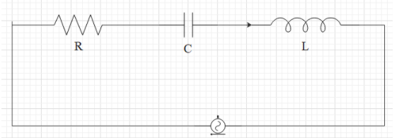
In a series resonant circuit, having $L,C\text{ and }R$ as its elements, the resonant current will be found to be as $i$. What will be the power dissipated in the circuit at resonance?
$\begin{align}
& A.{{i}^{2}}l\omega \\
& B.{{i}^{2}}R \\
& C.zero \\
& D.{{i}^{2}}C\omega \\
\end{align}$
Answer
572.1k+ views
Hint: The effective resistance of the circuit can be found by taking the square root of the sum of the square of the resistance and the square of the difference between the product of inductance and resonant frequency and the reciprocal of the product of the capacitance and the resonant frequency. Find the effective power by substituting the resonance frequency equation. Power dissipated will be a product of the square of the current and the effective resistance. This will help you in answering this question.
Complete answer:
it has been already mentioned in the question that the series resonant circuit is having $L,C\text{ and }R$ as its elements. The resonant current in the circuit has been found to be as $i$. The effective resistance of the circuit can be found by taking the square root of the sum of the square of the resistance and the square of the difference between the product of inductance and resonant frequency and the reciprocal of the product of the capacitance and the resonant frequency. This can be written as,
$X=\sqrt{{{R}^{2}}+{{\left( L\omega -\dfrac{1}{C\omega } \right)}^{2}}}$
At the resonance the angular frequency can be written as,
$\omega =\dfrac{1}{\sqrt{LC}}$
Therefore the effective resistance will become,
$X=R$
The power dissipated will be a product of the square of the current and the resistance.
$P={{i}^{2}}R$
Therefore the correct answer for the power dissipated has been obtained.
This has been mentioned as option B.
Note:
The primary difference between a capacitor and an inductor is that a capacitor will prevent a variation in voltage. But an inductor will prevent a variation in the current. The inductor is used to store energy in the form of a magnetic field, and the capacitor is used to store energy in the form of an electric field.
Recently Updated Pages
Master Class 12 Economics: Engaging Questions & Answers for Success
Master Class 12 Physics: Engaging Questions & Answers for Success
Master Class 12 English: Engaging Questions & Answers for Success
Master Class 12 Social Science: Engaging Questions & Answers for Success
Master Class 12 Maths: Engaging Questions & Answers for Success
Master Class 12 Business Studies: Engaging Questions & Answers for Success
Trending doubts
Which are the Top 10 Largest Countries of the World?
What are the major means of transport Explain each class 12 social science CBSE
Draw a labelled sketch of the human eye class 12 physics CBSE
Why cannot DNA pass through cell membranes class 12 biology CBSE
Differentiate between insitu conservation and exsitu class 12 biology CBSE
Draw a neat and well labeled diagram of TS of ovary class 12 biology CBSE