


In a common emitter amplifier circuit using n-p-n transistor, the phase difference between the input and output voltage will be:
A. \[{180^\circ }\]
B. ${45^\circ }$
C. ${90^\circ }$
D. ${135^\circ }$
Answer
603.9k+ views
Hint: In a common emitter amplifier, when base voltage increases, base current increases. It also causes an increase in the collector current which in turn causes a voltage drop in the collector resistor. Because the output is situated below the collector resistance. The output voltage will decrease as voltage drop across collector resistor increases, which results in some phase difference.
Complete answer:
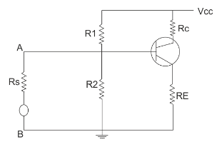
The phase relationship between the input and output voltages can be determined by considering the effect of a positive half cycle and negative half cycle separately.Consider the positive half cycle of input signal in which terminal A is positive w.r.t B. Due to this, two voltages, ac and dc will be adding each other, increasing forward bias on base emitter junction. This increases base current. The collector current is $\beta $ times the base current, hence the collector current will also increase. This increases the voltage drop across ${R_c}.$
Since,
${V_c} = {V_{cc}} - {I_c}{R_c}$
Therefore, increase in ${I_c}$ results in a drop in collector voltage ${V_c}$ as ${V_{cc}}$ is constant. Thus, as ${V_i}$ increases in a positive direction, ${V_o}$ goes in a negative direction and we get a negative half cycle of output voltage for positive half cycle at the input.In the negative half cycle of input, in which terminal A becomes negative w.r.t. terminal B, the ac and dc voltages will oppose each other, reducing forward bias on base-emitter p-n junction.
This reduces base current. Accordingly collector current and drop across ${R_c}$ both reduce, increasing the output voltage. Thus, we get positive half cycle at the output for negative half cycle at the input. Therefore, we can say that there is a phase shift of 180° between input and output voltages for a common emitter amplifier.
Hence option A is correct.
Note: These transistors are used as amplifiers. An amplifier is used to increase the small signal level; i.e. the amplifier is used to get a larger signal output from a small signal input. We will assume a sinusoidal signal at the input of the amplifier. At the output, the signal must remain sinusoidal in waveform, with frequency same as that of the input. To make the transistor work as an amplifier, it is to be biased to operate in the active region, i.e. base-emitter junction is to be forward biased, while base-collector junction to be reversed biased.
Complete answer:
The phase relationship between the input and output voltages can be determined by considering the effect of a positive half cycle and negative half cycle separately.Consider the positive half cycle of input signal in which terminal A is positive w.r.t B. Due to this, two voltages, ac and dc will be adding each other, increasing forward bias on base emitter junction. This increases base current. The collector current is $\beta $ times the base current, hence the collector current will also increase. This increases the voltage drop across ${R_c}.$
Since,
${V_c} = {V_{cc}} - {I_c}{R_c}$
Therefore, increase in ${I_c}$ results in a drop in collector voltage ${V_c}$ as ${V_{cc}}$ is constant. Thus, as ${V_i}$ increases in a positive direction, ${V_o}$ goes in a negative direction and we get a negative half cycle of output voltage for positive half cycle at the input.In the negative half cycle of input, in which terminal A becomes negative w.r.t. terminal B, the ac and dc voltages will oppose each other, reducing forward bias on base-emitter p-n junction.
This reduces base current. Accordingly collector current and drop across ${R_c}$ both reduce, increasing the output voltage. Thus, we get positive half cycle at the output for negative half cycle at the input. Therefore, we can say that there is a phase shift of 180° between input and output voltages for a common emitter amplifier.
Hence option A is correct.
Note: These transistors are used as amplifiers. An amplifier is used to increase the small signal level; i.e. the amplifier is used to get a larger signal output from a small signal input. We will assume a sinusoidal signal at the input of the amplifier. At the output, the signal must remain sinusoidal in waveform, with frequency same as that of the input. To make the transistor work as an amplifier, it is to be biased to operate in the active region, i.e. base-emitter junction is to be forward biased, while base-collector junction to be reversed biased.
Recently Updated Pages
Basicity of sulphurous acid and sulphuric acid are
Master Class 12 Economics: Engaging Questions & Answers for Success
Master Class 12 Biology: Engaging Questions & Answers for Success
Master Class 11 English: Engaging Questions & Answers for Success
Master Class 11 Physics: Engaging Questions & Answers for Success
Master Class 11 Computer Science: Engaging Questions & Answers for Success
Trending doubts
Draw a labelled sketch of the human eye class 12 physics CBSE
The chemical formula of tear gas is A CO Cl 2 B C 10 class 12 chemistry CBSE
Draw ray diagrams each showing i myopic eye and ii class 12 physics CBSE
Which are the Top 10 Largest Countries of the World?
Differentiate between homogeneous and heterogeneous class 12 chemistry CBSE
Which is the correct genotypic ratio of mendel dihybrid class 12 biology CBSE