


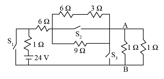
If the switches \[{S_1}\],\[{S_2}\] and \[{S_3}\] in the figure are arranged such that current through the battery is minimum, find the voltage across points A and B. (rounded off to nearest integer)
Answer
588k+ views
Hint: The above problem can be resolved by undertaking the circuit analysis for the given circuit diagram and applying the concept of the series as well as the parallel connections of the resistors accordingly. In the first switch, the resistor is connected in series with the net resistance across the switch second. Similarly, the third switch is also in series with that of the second and the first.
Complete step by step answer:
As we know that when all the switches in an electrical circuit are opened, then the magnitude of the current through the battery will be minimal.
The current through the circuit is given as,
\[I = \dfrac{V}{{{R_{net}}}}\]
Here, V is the source of the voltage supply and its value is given as 24 V. And \[{R_{net}}\] is the net resistance across the terminals A and B.
As the \[6\;\Omega \] resistance and the \[3\;\Omega \] resistance above \[{S_2}\] is in series and together forms a parallel
connection with the \[9\;\Omega \] resistance. Then the net resistance at \[{S_2}\] is,
\[\begin{array}{l}
{R_1} = 6\;\Omega + 3\;\Omega \\
{R_1} = 9\;\Omega
\end{array}\]
Further solving as,
\[\begin{array}{l}
\dfrac{1}{{{R_2}}} = \dfrac{1}{{9\;\Omega }} + \dfrac{1}{{9\;\Omega }}\\
{R_2} = \dfrac{9}{2}\;\Omega
\end{array}\]
Similarly the net resistance across the switch \[{S_3}\] is,
\[\begin{array}{c}
\dfrac{1}{{{R_3}}} = \dfrac{1}{{1\;\Omega }} + \dfrac{1}{{1\;\Omega }}\\
{R_3} = \dfrac{1}{2}\;\Omega
\end{array}\]
The net resistance across the terminal A B is,
\[\begin{array}{l}
{R_{net}} = 1\;\Omega + 6\;\Omega + \dfrac{9}{2}\;\Omega + \dfrac{1}{2}\;\Omega \\
{R_{net}} = 12\;\Omega
\end{array}\]
The current through the circuit is,
\[\begin{array}{l}
I = \dfrac{V}{{{R_{net}}}}\\
I = \dfrac{{24\;{\rm{V}}}}{{12\;\Omega }}\\
I = 2\;{\rm{A}}
\end{array}\]
Now, the voltage across the AB is,
\[\begin{array}{l}
{V_{AB}} = I \times {R_3}\\
{V_{AB}} = 2\;{\rm{A}} \times \dfrac{1}{2}\;\Omega \\
{V_{AB}} = 1\;{\rm{V}}
\end{array}\]
Therefore, the voltage across the terminal AB is 1 volts.
Note:
Try to understand the concept of the series and the parallel connection of the resistors. The given problem needs to be applied to the accurate analysis of the circuit. Moreover, the concept of Ohm's Law to identify the magnitude of current and the voltage supply also need to be remembered.
Recently Updated Pages
Master Class 12 Economics: Engaging Questions & Answers for Success
Master Class 12 Physics: Engaging Questions & Answers for Success
Master Class 12 English: Engaging Questions & Answers for Success
Master Class 12 Social Science: Engaging Questions & Answers for Success
Master Class 12 Maths: Engaging Questions & Answers for Success
Master Class 12 Business Studies: Engaging Questions & Answers for Success
Trending doubts
Which are the Top 10 Largest Countries of the World?
What are the major means of transport Explain each class 12 social science CBSE
Draw a labelled sketch of the human eye class 12 physics CBSE
Why cannot DNA pass through cell membranes class 12 biology CBSE
Differentiate between insitu conservation and exsitu class 12 biology CBSE
Draw a neat and well labeled diagram of TS of ovary class 12 biology CBSE