


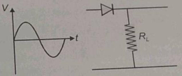
If in a p-n junction diode, a sinusoidal input signal is applied as shown. Then, the output signal across will be:
Answer
627.9k+ views
Hint: In this question, we need to use the working principle of a diode to solve. The setup displayed by the circuit diagram in the figure above measures the output across the semiconductor diode. The voltage source used here is alternating in nature.
Complete step by step answer:
In the given question, an alternating voltage source is the input signal source. The first half of the voltage-time graph that is above the time axis is a positive signal, while the other half of the signal that is below the time axis is a negative signal.
The semiconductor diode (the one shown in the diagram) operates when it is forward biased. When the diode is forward biased, it offers minimal resistance. The first part of the signal makes the diode operate in forward biased condition, so the same signal appears in the output.
In the second half of the signal, the diode operates in the reversed biased condition as the signal is negative. So, the diode offers infinite resistance, and hence no signal appears in the output. Again, when the positive signal goes into the diode, it appears in the output.
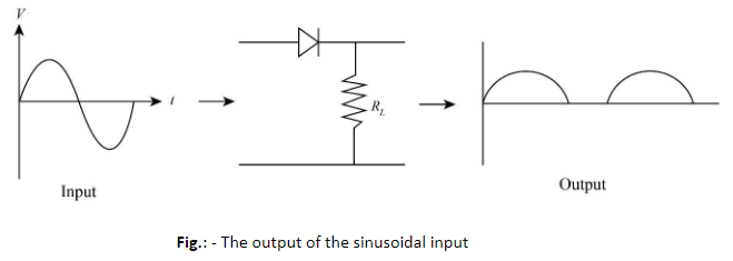
Therefore, we will receive an alternative voltage signal in which only the positive portions are present. In other words, we will receive a rectified version of the input signal as shown in the figure above.
Note: In the current question, we consider that the diode has a very small cut-in voltage. The cut-in voltage is considered to be small enough that it does not manifest itself in the output of the diode. If the cut-in voltage becomes comparable to the input signal, then we will lose a significant portion of the positive signal in overcoming the potential barrier. The negative part will still not appear in the output signal.
Complete step by step answer:
In the given question, an alternating voltage source is the input signal source. The first half of the voltage-time graph that is above the time axis is a positive signal, while the other half of the signal that is below the time axis is a negative signal.
The semiconductor diode (the one shown in the diagram) operates when it is forward biased. When the diode is forward biased, it offers minimal resistance. The first part of the signal makes the diode operate in forward biased condition, so the same signal appears in the output.
In the second half of the signal, the diode operates in the reversed biased condition as the signal is negative. So, the diode offers infinite resistance, and hence no signal appears in the output. Again, when the positive signal goes into the diode, it appears in the output.
Therefore, we will receive an alternative voltage signal in which only the positive portions are present. In other words, we will receive a rectified version of the input signal as shown in the figure above.
Note: In the current question, we consider that the diode has a very small cut-in voltage. The cut-in voltage is considered to be small enough that it does not manifest itself in the output of the diode. If the cut-in voltage becomes comparable to the input signal, then we will lose a significant portion of the positive signal in overcoming the potential barrier. The negative part will still not appear in the output signal.
Recently Updated Pages
Master Class 12 Business Studies: Engaging Questions & Answers for Success
Master Class 12 Chemistry: Engaging Questions & Answers for Success
Master Class 12 Biology: Engaging Questions & Answers for Success
Class 12 Question and Answer - Your Ultimate Solutions Guide
Master Class 11 English: Engaging Questions & Answers for Success
Master Class 11 Social Science: Engaging Questions & Answers for Success
Trending doubts
Which are the Top 10 Largest Countries of the World?
Draw a labelled sketch of the human eye class 12 physics CBSE
Differentiate between homogeneous and heterogeneous class 12 chemistry CBSE
Differentiate between Pyramid of energy and pyramid class 12 biology CBSE
Why is the cell called the structural and functional class 12 biology CBSE
Draw the diagram of the pyramid of energy Explain In class 12 biology CBSE