


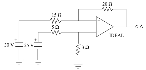
For the difference amplifier circuit shown, determine the output voltage at terminal $A$.
A. $ - 18.13\;{\rm{V}}$.
B. $ - 6.07\;{\rm{V}}$.
C. $6.07\;{\rm{V}}$.
D. $15.45\;{\rm{V}}$.
Answer
573.9k+ views
Hint:In this solution we will take the equivalent resistance when the resistances are connected in the parallel or series connection and will take the voltages of voltmeters to find out the output voltage at the given terminal.
Complete step by step answer:
Voltage ${V_1} = 30\;{\rm{V}}$.
Voltage ${V_2} = 25\;{\rm{V}}$.
Resistance ${R_1} = 15\;\Omega $.
Resistance ${R_2} = 20\;\Omega $.
Resistance ${R_3} = 5\;\Omega $.
Resistance ${R_4} = 3\;\Omega $.
When a circuit or device has a power gain more than one then that circuit is known as an amplifier. The amplifiers are mostly used in the electronic components.
Express the formula of the output voltage of the difference amplifier.
${V_A} = - \dfrac{{{R_2}}}{{{R_1}}}{V_1} + \left( {\dfrac{{{R_4}}}{{{R_3} + {R_4}}}} \right)\left( {1 + \dfrac{{{R_2}}}{{{R_1}}}} \right){V_2}$
Here,
${V_A}$ is the voltage at $A$.
${R_2}$,${R_1}$,${R_3}$ and ${R_4}$ are the resistance.
$V{}_1$ and ${V_2}$ are the voltage.
Substitute $30\;{\rm{V}}$ for ${V_1}$ , $25\;{\rm{V}}$ for ${V_2}$ , $15\;\Omega $ for ${R_1}$ , $20\;\Omega $ for ${R_2}$, $5\;\Omega $ for ${R_3}$ and $3\;\Omega $ for ${R_4}$ to obtain the voltage at $A$.
$
{V_A} = - \dfrac{{20\;\Omega }}{{15\;\Omega }}\left( {30\;{\rm{V}}} \right) + \left( {\dfrac{{3\;\Omega }}{{3\;\Omega + 5\;\Omega }}} \right)\left( {1 + \dfrac{{20\;\Omega }}{{15\;\Omega }}} \right)\left( {25\;{\rm{V}}} \right)\\
\Rightarrow{V_A} = - 40 + \dfrac{{21}}{{25}}\left( {25\;{\rm{V}}} \right)\\
\Rightarrow{V_A} = - 40 + \dfrac{{525}}{{24}}\;\;{\rm{V}}\\
\Rightarrow{V_A} = - 40 + 21.875\;{\rm{V}}\\
\Rightarrow {V_A} = - 18.125\;{\rm{V}}\\
\therefore{V_A} = - 18.13\;{\rm{V}}
$
Therefore, the correct option is (A).
Note:While solving this type of questions make sure that the prediction of parallel or series connection must be right to find out the equivalent resistance otherwise the solution will be wrong.
Recently Updated Pages
Master Class 12 Economics: Engaging Questions & Answers for Success
Master Class 12 Physics: Engaging Questions & Answers for Success
Master Class 12 English: Engaging Questions & Answers for Success
Master Class 12 Social Science: Engaging Questions & Answers for Success
Master Class 12 Maths: Engaging Questions & Answers for Success
Master Class 12 Business Studies: Engaging Questions & Answers for Success
Trending doubts
Which are the Top 10 Largest Countries of the World?
What are the major means of transport Explain each class 12 social science CBSE
Draw a labelled sketch of the human eye class 12 physics CBSE
Why cannot DNA pass through cell membranes class 12 biology CBSE
Differentiate between insitu conservation and exsitu class 12 biology CBSE
Draw a neat and well labeled diagram of TS of ovary class 12 biology CBSE