


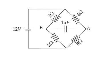
Find ${V_A} - {V_B}$ in the given diagram.
Answer
600.9k+ views
Hint: Here the two resistors connected to point B and the two resistors connected to point A make up two serial connections. These two serial connections then make up a parallel connection. At steady-state, no current will pass through the capacitor. So the potential difference across A and B can be obtained by determining the current through the two arms of the bridge arrangement.
Formulas used:
-The effective resistance in a series connection between two resistors is given by, ${R_{eff}} = {R_1} + {R_2}$ where ${R_1}$ and ${R_2}$ are the resistances of the two resistors.
-The effective resistance in a parallel connection between two resistors is given by, ${R_{eff}} = \dfrac{{{R_1}{R_2}}}{{{R_1} + {R_2}}}$ where ${R_1}$ and ${R_2}$ are the resistances of the two resistors.
-Ohm’s law gives the current in a circuit as $I = \dfrac{V}{R}$ where $V$ is the potential difference and $R$ is the resistance offered to the flow of current.
Complete step by step solution:
Step 1: Sketch the given circuit diagram and mark the current through each arm.
Let the total current in the circuit be $I$ . This current then splits into ${i_1}$ and ${i_2}$ to pass through two arms of the bridge arrangement of resistors. The voltage across the circuit is given to be $V = 12{\text{V}}$ .
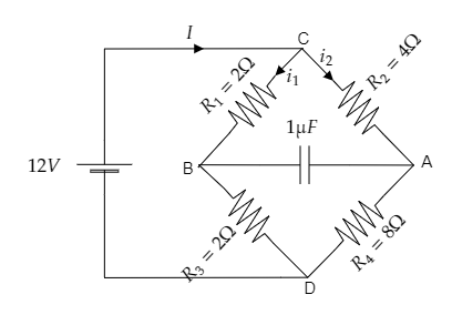
As seen from the above figure, ${R_1} = 2\Omega $ and ${R_3} = 2\Omega $ are connected in series. Also, ${R_2} = 4\Omega $ and ${R_4} = 8\Omega $ are connected in series.
The current through arm CB is ${i_1}$ and the current through arm CA is ${i_2}$ .
Step 2: Express the effective resistance offered by the circuit.
Now, the effective resistance across the left side of junctions C and D will be
${R_{eff1}} = {R_1} + {R_3}$ ------- (1)
Substituting for ${R_1} = 2\Omega $ and ${R_3} = 2\Omega $ in equation (1) we get, ${R_{eff1}} = 2 + 2 = 4\Omega $ .
Thus the effective resistance to the left of junctions C and D is ${R_{eff1}} = 4\Omega $ .
The effective resistance across the right side of junctions C and D will be
${R_{eff2}} = {R_2} + {R_4}$ ------- (2)
Substituting for ${R_2} = 4\Omega $ and ${R_4} = 8\Omega $ in equation (2) we get, ${R_{eff2}} = 4 + 8 = 12\Omega $ .
Thus the effective resistance to the right of junctions C and D is ${R_{eff2}} = 12\Omega $ .
At steady-state, no current will pass through the capacitor in the circuit so we can discard it.
Then as the two obtained effective resistances on either side of the junctions C and D form a parallel connection, the effective resistance of the entire circuit will be ${R_{eff}} = \dfrac{{{R_{eff1}}{R_{eff2}}}}{{{R_{eff1}} + {R_{eff2}}}}$ ------- (3)
Substituting for ${R_{eff1}} = 4\Omega $ and ${R_{eff2}} = 12\Omega $ in equation (3) we get, ${R_{eff}} = \dfrac{{4 \times 12}}{{4 + 12}} = 3\Omega $
Thus the effective resistance offered by the circuit is obtained to be ${R_{eff}} = 3\Omega $ .
Step 3: Express the total current in the circuit.
Ohm’s law gives the current in the given circuit as $I = \dfrac{V}{{{R_{eff}}}}$ ------- (4)
Substituting for $V = 12{\text{V}}$ and ${R_{eff}} = 3\Omega $ in equation (4) we get, $I = \dfrac{{12}}{3} = 4{\text{A}}$ .
So the total current in the circuit will be $I = 4{\text{A}}$ .
Step 4: Express the current ${i_1}$ and ${i_2}$ based on Ohm’s law.
The current across arm CB will be the current across the effective resistance to the left of the junctions C and D i.e., ${i_1} = \dfrac{V}{{{R_{eff1}}}}$ ------- (5)
Substituting for $V = 12{\text{V}}$ and ${R_{eff1}} = 4\Omega $ in equation (5) we get, ${i_1} = \dfrac{{12}}{4} = 3{\text{A}}$
The current across arm CB is ${i_1} = 3{\text{A}}$ .
The current across arm CA will be the current across the effective resistance to the right of the junctions C and D i.e., ${i_2} = \dfrac{V}{{{R_{eff2}}}}$ ------- (6)
Substituting for $V = 12{\text{V}}$ and ${R_{eff2}} = 12\Omega $ in equation (6) we get, ${i_2} = \dfrac{{12}}{{12}} = 1{\text{A}}$
The current across arm CA is ${i_2} = 1{\text{A}}$ .
Step 5: Express the potential at A and B to obtain the required potential difference.
Now the potential at A will be the potential drop across the resistor ${R_2}$ .
ie., ${V_A} = {i_2}{R_2}$ --------- (7)
Substituting for ${i_2} = 1{\text{A}}$ and ${R_2} = 4\Omega $ in equation (7) we get, the potential at A as ${V_A} = 1 \times 4 = 4{\text{V}}$.
Similarly, the potential at B will be the potential drop across the resistor ${R_1}$ .
ie., ${V_B} = {i_1}{R_1}$ --------- (8)
Substituting for ${i_1} = 3{\text{A}}$ and ${R_1} = 2\Omega $ in equation (8) we get, the potential at B as ${V_B} = 3 \times 2 = 6{\text{V}}$.
Then the potential difference between point A and B will be ${V_A} - {V_B} = 4 - 6 = - 2{\text{V}}$ .
$\therefore $ the magnitude of the required potential difference is ${V_A} - {V_B} = 2{\text{V}}$ .
Note: In a parallel connection of two resistors, the potential difference across the two resistors will be the same, however, the current through the two resistors will be different. This concept is used in step 4 to express the currents ${i_1}$ and ${i_2}$ through the two arms CB and CA of the bridge arrangement of the resistors.
Formulas used:
-The effective resistance in a series connection between two resistors is given by, ${R_{eff}} = {R_1} + {R_2}$ where ${R_1}$ and ${R_2}$ are the resistances of the two resistors.
-The effective resistance in a parallel connection between two resistors is given by, ${R_{eff}} = \dfrac{{{R_1}{R_2}}}{{{R_1} + {R_2}}}$ where ${R_1}$ and ${R_2}$ are the resistances of the two resistors.
-Ohm’s law gives the current in a circuit as $I = \dfrac{V}{R}$ where $V$ is the potential difference and $R$ is the resistance offered to the flow of current.
Complete step by step solution:
Step 1: Sketch the given circuit diagram and mark the current through each arm.
Let the total current in the circuit be $I$ . This current then splits into ${i_1}$ and ${i_2}$ to pass through two arms of the bridge arrangement of resistors. The voltage across the circuit is given to be $V = 12{\text{V}}$ .
As seen from the above figure, ${R_1} = 2\Omega $ and ${R_3} = 2\Omega $ are connected in series. Also, ${R_2} = 4\Omega $ and ${R_4} = 8\Omega $ are connected in series.
The current through arm CB is ${i_1}$ and the current through arm CA is ${i_2}$ .
Step 2: Express the effective resistance offered by the circuit.
Now, the effective resistance across the left side of junctions C and D will be
${R_{eff1}} = {R_1} + {R_3}$ ------- (1)
Substituting for ${R_1} = 2\Omega $ and ${R_3} = 2\Omega $ in equation (1) we get, ${R_{eff1}} = 2 + 2 = 4\Omega $ .
Thus the effective resistance to the left of junctions C and D is ${R_{eff1}} = 4\Omega $ .
The effective resistance across the right side of junctions C and D will be
${R_{eff2}} = {R_2} + {R_4}$ ------- (2)
Substituting for ${R_2} = 4\Omega $ and ${R_4} = 8\Omega $ in equation (2) we get, ${R_{eff2}} = 4 + 8 = 12\Omega $ .
Thus the effective resistance to the right of junctions C and D is ${R_{eff2}} = 12\Omega $ .
At steady-state, no current will pass through the capacitor in the circuit so we can discard it.
Then as the two obtained effective resistances on either side of the junctions C and D form a parallel connection, the effective resistance of the entire circuit will be ${R_{eff}} = \dfrac{{{R_{eff1}}{R_{eff2}}}}{{{R_{eff1}} + {R_{eff2}}}}$ ------- (3)
Substituting for ${R_{eff1}} = 4\Omega $ and ${R_{eff2}} = 12\Omega $ in equation (3) we get, ${R_{eff}} = \dfrac{{4 \times 12}}{{4 + 12}} = 3\Omega $
Thus the effective resistance offered by the circuit is obtained to be ${R_{eff}} = 3\Omega $ .
Step 3: Express the total current in the circuit.
Ohm’s law gives the current in the given circuit as $I = \dfrac{V}{{{R_{eff}}}}$ ------- (4)
Substituting for $V = 12{\text{V}}$ and ${R_{eff}} = 3\Omega $ in equation (4) we get, $I = \dfrac{{12}}{3} = 4{\text{A}}$ .
So the total current in the circuit will be $I = 4{\text{A}}$ .
Step 4: Express the current ${i_1}$ and ${i_2}$ based on Ohm’s law.
The current across arm CB will be the current across the effective resistance to the left of the junctions C and D i.e., ${i_1} = \dfrac{V}{{{R_{eff1}}}}$ ------- (5)
Substituting for $V = 12{\text{V}}$ and ${R_{eff1}} = 4\Omega $ in equation (5) we get, ${i_1} = \dfrac{{12}}{4} = 3{\text{A}}$
The current across arm CB is ${i_1} = 3{\text{A}}$ .
The current across arm CA will be the current across the effective resistance to the right of the junctions C and D i.e., ${i_2} = \dfrac{V}{{{R_{eff2}}}}$ ------- (6)
Substituting for $V = 12{\text{V}}$ and ${R_{eff2}} = 12\Omega $ in equation (6) we get, ${i_2} = \dfrac{{12}}{{12}} = 1{\text{A}}$
The current across arm CA is ${i_2} = 1{\text{A}}$ .
Step 5: Express the potential at A and B to obtain the required potential difference.
Now the potential at A will be the potential drop across the resistor ${R_2}$ .
ie., ${V_A} = {i_2}{R_2}$ --------- (7)
Substituting for ${i_2} = 1{\text{A}}$ and ${R_2} = 4\Omega $ in equation (7) we get, the potential at A as ${V_A} = 1 \times 4 = 4{\text{V}}$.
Similarly, the potential at B will be the potential drop across the resistor ${R_1}$ .
ie., ${V_B} = {i_1}{R_1}$ --------- (8)
Substituting for ${i_1} = 3{\text{A}}$ and ${R_1} = 2\Omega $ in equation (8) we get, the potential at B as ${V_B} = 3 \times 2 = 6{\text{V}}$.
Then the potential difference between point A and B will be ${V_A} - {V_B} = 4 - 6 = - 2{\text{V}}$ .
$\therefore $ the magnitude of the required potential difference is ${V_A} - {V_B} = 2{\text{V}}$ .
Note: In a parallel connection of two resistors, the potential difference across the two resistors will be the same, however, the current through the two resistors will be different. This concept is used in step 4 to express the currents ${i_1}$ and ${i_2}$ through the two arms CB and CA of the bridge arrangement of the resistors.
Recently Updated Pages
Master Class 12 Business Studies: Engaging Questions & Answers for Success
Master Class 12 Biology: Engaging Questions & Answers for Success
Master Class 12 Chemistry: Engaging Questions & Answers for Success
Class 12 Question and Answer - Your Ultimate Solutions Guide
Master Class 11 Social Science: Engaging Questions & Answers for Success
Master Class 11 English: Engaging Questions & Answers for Success
Trending doubts
Which are the Top 10 Largest Countries of the World?
Draw a labelled sketch of the human eye class 12 physics CBSE
Name the crygenes that control cotton bollworm and class 12 biology CBSE
Differentiate between homogeneous and heterogeneous class 12 chemistry CBSE
Ribosomal RNA is actively synthesised in A Nucleoplasm class 12 biology CBSE
How many molecules of ATP and NADPH are required information class 12 biology CBSE