


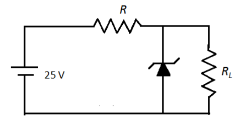
Find the minimum load resistance which can be used for the zener diode as shown in figure. Given, \[{V_Z} = 10\,V\], \[{R_Z} = 0\,\Omega \], \[R = 450\,\Omega \], \[{I_z}\left( {\min } \right) = 2\,mA\]and \[{I_z}\left( {\max } \right) = 60\,mA\].
(A) \[0\,\Omega \]
(B) \[333.3\,\Omega \]
(C) \[31.95\,\Omega \]
(D) \[319.5\,\Omega \]
Answer
600.6k+ views
Hint:Calculate the total current in the circuit using KVL. This current divides at the junction and passes separately through the zener diode and load resistor. For the load resistance to be a minimum, the current passing through it must be a maximum. Calculate the value of current passing through the load resistor using Ohm’s law.
Formula used:
According to Ohm’s law, the voltage across the resistor R is,
\[V = IR\]
Here, I is the current.
Complete step by step answer:
To determine the total current in the circuit, we can apply Kirchhoff’s voltage law in the first loop containing resistor and zener diode as follows,
\[25 - IR - {V_Z} = 0\]
Here, I is the total current in the resistor R and \[{V_Z}\] is the voltage drop across zener diode.We substitute \[R = 450\,\Omega \] and \[{V_Z} = 10\,V\] in the above equation.
\[25 - I\left( {450} \right) - 10 = 0\]
\[ \Rightarrow I = 0.0333\,A\]
\[ \Rightarrow I = 33.3\,mA\]
We apply Kirchhoff’s current law at the point A in the following circuit as follows,
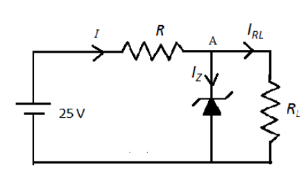
The total current in the circuit is,
\[I = {I_{RL}} + {I_Z}\]
Here, \[{I_{RL}}\] is the current through load resistance and \[{I_Z}\] is the current through zener diode.For the maximum current through the load resistor, the current through the zener diode should be the minimum. Therefore,
\[I = {I_{RL}}\left( {\max } \right) + {I_Z}\left( {\min } \right)\]
We substitute \[{I_z}\left( {\min } \right) = 2\,mA\]and \[I = 33.3\,mA\] in the above equation.
\[33.3 = {I_{RL}}\left( {\max } \right) + 2\]
\[ \Rightarrow {I_{RL}}\left( {\max } \right) = 31.3\,mA\]
We know that the voltage across the parallel combination remains the same. Therefore, the voltage across the load resistance should be equal to the voltage across the zener diode.
We calculate the load resistance as follows,
\[{R_L} = \dfrac{{{V_{RL}}}}{{{I_{RL}}\left( {\max } \right)}}\]
We substitute \[{V_{RL}} = 10\,V\] and \[{I_{RL}}\left( {\max } \right) = 31.3\,mA\] in the above equation.
\[{R_L} = \dfrac{{10\,\Omega }}{{31.3\,mA}} = \dfrac{{10\,\Omega }}{{0.313\,A}}\]
\[ \therefore {R_L} = 319.5\,\Omega \]
Therefore, the minimum value of load resistance is \[319.5\,\Omega \].So, the correct answer is option (D).
Note: We know that KVL states that the sum of voltage drop across each component in the circuit. If there is a drop in the voltage, then the sign of voltage should be negative and if there is addition of voltage then the sign should be positive. In the above circuit, there is drop in the voltage across the resistor and zener diode. The current does not pass through the lower terminal of the zener diode because the zener diode works in reverse bias mode.
Formula used:
According to Ohm’s law, the voltage across the resistor R is,
\[V = IR\]
Here, I is the current.
Complete step by step answer:
To determine the total current in the circuit, we can apply Kirchhoff’s voltage law in the first loop containing resistor and zener diode as follows,
\[25 - IR - {V_Z} = 0\]
Here, I is the total current in the resistor R and \[{V_Z}\] is the voltage drop across zener diode.We substitute \[R = 450\,\Omega \] and \[{V_Z} = 10\,V\] in the above equation.
\[25 - I\left( {450} \right) - 10 = 0\]
\[ \Rightarrow I = 0.0333\,A\]
\[ \Rightarrow I = 33.3\,mA\]
We apply Kirchhoff’s current law at the point A in the following circuit as follows,
The total current in the circuit is,
\[I = {I_{RL}} + {I_Z}\]
Here, \[{I_{RL}}\] is the current through load resistance and \[{I_Z}\] is the current through zener diode.For the maximum current through the load resistor, the current through the zener diode should be the minimum. Therefore,
\[I = {I_{RL}}\left( {\max } \right) + {I_Z}\left( {\min } \right)\]
We substitute \[{I_z}\left( {\min } \right) = 2\,mA\]and \[I = 33.3\,mA\] in the above equation.
\[33.3 = {I_{RL}}\left( {\max } \right) + 2\]
\[ \Rightarrow {I_{RL}}\left( {\max } \right) = 31.3\,mA\]
We know that the voltage across the parallel combination remains the same. Therefore, the voltage across the load resistance should be equal to the voltage across the zener diode.
We calculate the load resistance as follows,
\[{R_L} = \dfrac{{{V_{RL}}}}{{{I_{RL}}\left( {\max } \right)}}\]
We substitute \[{V_{RL}} = 10\,V\] and \[{I_{RL}}\left( {\max } \right) = 31.3\,mA\] in the above equation.
\[{R_L} = \dfrac{{10\,\Omega }}{{31.3\,mA}} = \dfrac{{10\,\Omega }}{{0.313\,A}}\]
\[ \therefore {R_L} = 319.5\,\Omega \]
Therefore, the minimum value of load resistance is \[319.5\,\Omega \].So, the correct answer is option (D).
Note: We know that KVL states that the sum of voltage drop across each component in the circuit. If there is a drop in the voltage, then the sign of voltage should be negative and if there is addition of voltage then the sign should be positive. In the above circuit, there is drop in the voltage across the resistor and zener diode. The current does not pass through the lower terminal of the zener diode because the zener diode works in reverse bias mode.
Recently Updated Pages
Master Class 12 Business Studies: Engaging Questions & Answers for Success
Master Class 12 Chemistry: Engaging Questions & Answers for Success
Master Class 12 Biology: Engaging Questions & Answers for Success
Class 12 Question and Answer - Your Ultimate Solutions Guide
Master Class 11 English: Engaging Questions & Answers for Success
Master Class 11 Maths: Engaging Questions & Answers for Success
Trending doubts
Which is more stable and why class 12 chemistry CBSE
Which are the Top 10 Largest Countries of the World?
Draw a labelled sketch of the human eye class 12 physics CBSE
Differentiate between homogeneous and heterogeneous class 12 chemistry CBSE
What are the major means of transport Explain each class 12 social science CBSE
Sulphuric acid is known as the king of acids State class 12 chemistry CBSE