


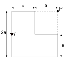
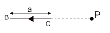
Find the magnetic field $ \vec B $ at the point $ P $ in the figure.
Answer
552k+ views
Hint :To find the magnetic field here, we will split open the loop considering every component of the loop separately. As all the components here are straight wires, we can use the formula for the magnetic field of a wire at a distance $ y $ from the wire i.e. $ B = \dfrac{{{\mu _0}}}{{4\pi }}\dfrac{I}{y}\left[ {\sin {\theta _1} + \sin {\theta _2}} \right] $ and take the sum of the magnetic field for all the wires.
Complete Step By Step Answer:
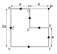
To have a better understanding of the diagram given here, let us label all the components and show the direction of current in each of them as shown below;
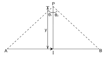
Now, before splitting the diagram, let us understand the formula for the magnetic field of a straight wire,
$ B = \dfrac{{{\mu _0}}}{{4\pi }}\dfrac{I}{y}\left[ {\sin {\theta _1} + \sin {\theta _2}} \right] $
Where, $ I $ is the current passing through the wire
$ y $ is the perpendicular distance of the point from the wire at which we want to find the magnetic field.
$ {\theta _1} $ is the angle between the perpendicular distance line and the line connecting one end of the wire to the external point.
$ {\theta _2} $ is the angle between the perpendicular distance line and the line connecting another end of the wire to the external point.
Consider the figure below to understand the terminologies;
Also, the direction of a magnetic field at the point can be found by Right Hand Rule i.e. by pointing the thumb in the direction of the current, the movement of fingers show the direction of the magnetic field. For the given sum, let us consider the magnetic field going inside the paper as positive and the magnetic field coming out of the paper as negative.
Now, let us find the magnetic field for the point $ P $ in the given sum by considering individual components.
Consider the component $ A\;B $ as shown in the figure below,
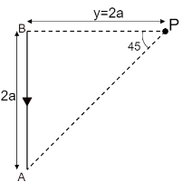
The current passing through the component is $ I $ .
The perpendicular distance of the point $ P $ from the wire is $ y = 2a $ as shown in the figure.
As the perpendicular line intersects the wire at the end, the angle between the perpendicular and the line connecting the point and end of the wire i.e. $ {\theta _1} = 0 $
The perpendicular distance is equal to the length of the wire here, hence from the figure, the angle between perpendicular and the line connecting another end of wire and external point i.e. $ {\theta _2} = 45^\circ $
Substituting these values in the equation of magnetic field,
$ \therefore B = \dfrac{{{\mu _0}}}{{4\pi }}\dfrac{I}{{(2a)}}\left[ {\sin 0^\circ + \sin 45^\circ } \right] $
$ \therefore {B_{AB}} = \dfrac{{{\mu _0}}}{{4\pi }}\dfrac{I}{{(2a)}}\left[ {\dfrac{1}{{\sqrt 2 }}} \right] $ …… $ (1) $
By pointing the thumb in the direction of the current, the fingers on the right side of the wire point out.
Hence, we will consider the magnetic field to be coming out and hence negative for this component.
Consider the component $ F\;A $ as shown in the figure below,
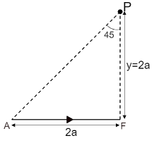
The current passing through the component is $ I $ .
The perpendicular distance of the point $ P $ from the wire is $ y = 2a $ as shown in the figure.
The perpendicular distance is equal to the length of the wire here, hence from the figure, the angle between perpendicular and the line connecting end of wire and external point i.e. $ {\theta _1} = 45^\circ $
As the perpendicular line intersects the wire at the end, the angle between the perpendicular and the line connecting the point and another end of the wire i.e. $ {\theta _2} = 0 $
Substituting these values in the equation of magnetic field,
$ \therefore B = \dfrac{{{\mu _0}}}{{4\pi }}\dfrac{I}{{(2a)}}\left[ {\sin 45^\circ + \sin 0^\circ } \right] $
$ \therefore {B_{FA}} = \dfrac{{{\mu _0}}}{{4\pi }}\dfrac{I}{{(2a)}}\left[ {\dfrac{1}{{\sqrt 2 }}} \right] $ …… $ (2) $
By pointing the thumb in the direction of the current, the fingers above the wire point out.
Hence, we will consider the magnetic field to be coming out and hence negative for this component.
Consider the component $ E\;F $ as shown in the figure below,
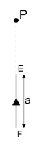
We know that the magnetic field lines for a straight wire are circular around the wire.
As for this component, the point lies on the axis of the wire. Hence, the point does not cut the magnetic field lines of this component.
$ \therefore {B_{EF}} = 0 $ …… $ (3) $
Consider the component $ D\;E $ as shown in the figure below,
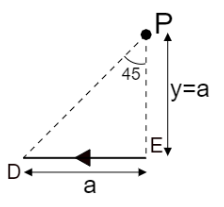
The current passing through the component is $ I $ .
The perpendicular distance of the point $ P $ from the wire is $ y = a $ as shown in the figure.
The perpendicular distance is equal to the length of the wire here, hence from the figure, the angle between perpendicular and the line connecting end of wire and external point i.e. $ {\theta _1} = 45^\circ $
As the perpendicular line intersects the wire at the end, the angle between the perpendicular and the line connecting the point and another end of the wire i.e. $ {\theta _2} = 0 $
Substituting these values in the equation of magnetic field,
$ \therefore B = \dfrac{{{\mu _0}}}{{4\pi }}\dfrac{I}{{(a)}}\left[ {\sin 45^\circ + \sin 0^\circ } \right] $
$ \therefore {B_{DE}} = \dfrac{{{\mu _0}}}{{4\pi }}\dfrac{I}{{(a)}}\left[ {\dfrac{1}{{\sqrt 2 }}} \right] $ …… $ (4) $
By pointing the thumb in the direction of the current, the fingers above the wire point in.
Hence, we will consider the magnetic field to be going in and hence positive for this component.
Consider the component $ C\;D $ as shown in the figure below,
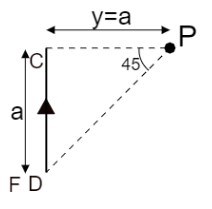
The current passing through the component is $ I $ .
The perpendicular distance of the point $ P $ from the wire is $ y = a $ as shown in the figure.
As the perpendicular line intersects the wire at the end, the angle between the perpendicular and the line connecting the point and another end of the wire i.e. $ {\theta _1} = 0 $
The perpendicular distance is equal to the length of the wire here, hence from the figure, the angle between perpendicular and the line connecting end of wire and external point i.e. $ {\theta _2} = 45^\circ $
Substituting these values in the equation of magnetic field,
$ \therefore B = \dfrac{{{\mu _0}}}{{4\pi }}\dfrac{I}{{(a)}}\left[ {\sin 0^\circ + \sin 45^\circ } \right] $
$ \therefore {B_{CD}} = \dfrac{{{\mu _0}}}{{4\pi }}\dfrac{I}{{(a)}}\left[ {\dfrac{1}{{\sqrt 2 }}} \right] $ …… $ (5) $
By pointing the thumb in the direction of the current, the fingers on the right-side point in.
Hence, we will consider the magnetic field to be going in and hence positive for this component.
Consider the component $ B\;C $ as shown in the figure below,
We know that the magnetic field lines for a straight wire are circular around the wire.
As for this component, the point lies on the axis of the wire. Hence, the point does not cut the magnetic field lines of this component.
$ \therefore {B_{BC}} = 0 $ …… $ (6) $
Hence, for equation $ (1) $ and $ (2) $ , the magnetic field is negative and for the equation $ (4) $ and $ (5) $ is positive.
Hence, taking the algebraic sum of all the components,
$ B = - {B_{AB}} - {B_{FA}} + {B_{EF}} + {B_{DE}} + {B_{CD}} + {B_{BC}} $
Substituting the values of the magnetic fields,
$ \therefore B = - \dfrac{{{\mu _0}}}{{4\pi }}\dfrac{I}{{(2a)}}\left[ {\dfrac{1}{{\sqrt 2 }}} \right] - \dfrac{{{\mu _0}}}{{4\pi }}\dfrac{I}{{(2a)}}\left[ {\dfrac{1}{{\sqrt 2 }}} \right] + 0 + \dfrac{{{\mu _0}}}{{4\pi }}\dfrac{I}{{(a)}}\left[ {\dfrac{1}{{\sqrt 2 }}} \right] + \dfrac{{{\mu _0}}}{{4\pi }}\dfrac{I}{{(a)}}\left[ {\dfrac{1}{{\sqrt 2 }}} \right] + 0 $
Taking the common terms out of the bracket,
$ \therefore B = \dfrac{{{\mu _0}I}}{{4\pi }}\left( {\dfrac{1}{{\sqrt 2 }}} \right)\left[ {\dfrac{1}{a} + \dfrac{1}{a} - \dfrac{1}{{2a}} - \dfrac{1}{{2a}}} \right] $
$ \therefore B = \dfrac{{{\mu _0}I}}{{4\pi }}\left( {\dfrac{1}{{\sqrt 2 }}} \right)\left[ {\dfrac{1}{a}} \right] $
Hence, the magnetic field of the loop at the point P is
$ \therefore B = \dfrac{{{\mu _0}I}}{{4\pi a}}\left( {\dfrac{1}{{\sqrt 2 }}} \right) $
Note :
The magnetic field for a straight wire is in the form of a cylinder wrapped around it. Hence, if the external point lies on the axis of the wire, we can consider it a part of the extended wire, and hence the magnetic field of the wire at the point is zero.
Complete Step By Step Answer:
To have a better understanding of the diagram given here, let us label all the components and show the direction of current in each of them as shown below;
Now, before splitting the diagram, let us understand the formula for the magnetic field of a straight wire,
$ B = \dfrac{{{\mu _0}}}{{4\pi }}\dfrac{I}{y}\left[ {\sin {\theta _1} + \sin {\theta _2}} \right] $
Where, $ I $ is the current passing through the wire
$ y $ is the perpendicular distance of the point from the wire at which we want to find the magnetic field.
$ {\theta _1} $ is the angle between the perpendicular distance line and the line connecting one end of the wire to the external point.
$ {\theta _2} $ is the angle between the perpendicular distance line and the line connecting another end of the wire to the external point.
Consider the figure below to understand the terminologies;
Also, the direction of a magnetic field at the point can be found by Right Hand Rule i.e. by pointing the thumb in the direction of the current, the movement of fingers show the direction of the magnetic field. For the given sum, let us consider the magnetic field going inside the paper as positive and the magnetic field coming out of the paper as negative.
Now, let us find the magnetic field for the point $ P $ in the given sum by considering individual components.
Consider the component $ A\;B $ as shown in the figure below,
The current passing through the component is $ I $ .
The perpendicular distance of the point $ P $ from the wire is $ y = 2a $ as shown in the figure.
As the perpendicular line intersects the wire at the end, the angle between the perpendicular and the line connecting the point and end of the wire i.e. $ {\theta _1} = 0 $
The perpendicular distance is equal to the length of the wire here, hence from the figure, the angle between perpendicular and the line connecting another end of wire and external point i.e. $ {\theta _2} = 45^\circ $
Substituting these values in the equation of magnetic field,
$ \therefore B = \dfrac{{{\mu _0}}}{{4\pi }}\dfrac{I}{{(2a)}}\left[ {\sin 0^\circ + \sin 45^\circ } \right] $
$ \therefore {B_{AB}} = \dfrac{{{\mu _0}}}{{4\pi }}\dfrac{I}{{(2a)}}\left[ {\dfrac{1}{{\sqrt 2 }}} \right] $ …… $ (1) $
By pointing the thumb in the direction of the current, the fingers on the right side of the wire point out.
Hence, we will consider the magnetic field to be coming out and hence negative for this component.
Consider the component $ F\;A $ as shown in the figure below,
The current passing through the component is $ I $ .
The perpendicular distance of the point $ P $ from the wire is $ y = 2a $ as shown in the figure.
The perpendicular distance is equal to the length of the wire here, hence from the figure, the angle between perpendicular and the line connecting end of wire and external point i.e. $ {\theta _1} = 45^\circ $
As the perpendicular line intersects the wire at the end, the angle between the perpendicular and the line connecting the point and another end of the wire i.e. $ {\theta _2} = 0 $
Substituting these values in the equation of magnetic field,
$ \therefore B = \dfrac{{{\mu _0}}}{{4\pi }}\dfrac{I}{{(2a)}}\left[ {\sin 45^\circ + \sin 0^\circ } \right] $
$ \therefore {B_{FA}} = \dfrac{{{\mu _0}}}{{4\pi }}\dfrac{I}{{(2a)}}\left[ {\dfrac{1}{{\sqrt 2 }}} \right] $ …… $ (2) $
By pointing the thumb in the direction of the current, the fingers above the wire point out.
Hence, we will consider the magnetic field to be coming out and hence negative for this component.
Consider the component $ E\;F $ as shown in the figure below,
We know that the magnetic field lines for a straight wire are circular around the wire.
As for this component, the point lies on the axis of the wire. Hence, the point does not cut the magnetic field lines of this component.
$ \therefore {B_{EF}} = 0 $ …… $ (3) $
Consider the component $ D\;E $ as shown in the figure below,
The current passing through the component is $ I $ .
The perpendicular distance of the point $ P $ from the wire is $ y = a $ as shown in the figure.
The perpendicular distance is equal to the length of the wire here, hence from the figure, the angle between perpendicular and the line connecting end of wire and external point i.e. $ {\theta _1} = 45^\circ $
As the perpendicular line intersects the wire at the end, the angle between the perpendicular and the line connecting the point and another end of the wire i.e. $ {\theta _2} = 0 $
Substituting these values in the equation of magnetic field,
$ \therefore B = \dfrac{{{\mu _0}}}{{4\pi }}\dfrac{I}{{(a)}}\left[ {\sin 45^\circ + \sin 0^\circ } \right] $
$ \therefore {B_{DE}} = \dfrac{{{\mu _0}}}{{4\pi }}\dfrac{I}{{(a)}}\left[ {\dfrac{1}{{\sqrt 2 }}} \right] $ …… $ (4) $
By pointing the thumb in the direction of the current, the fingers above the wire point in.
Hence, we will consider the magnetic field to be going in and hence positive for this component.
Consider the component $ C\;D $ as shown in the figure below,
The current passing through the component is $ I $ .
The perpendicular distance of the point $ P $ from the wire is $ y = a $ as shown in the figure.
As the perpendicular line intersects the wire at the end, the angle between the perpendicular and the line connecting the point and another end of the wire i.e. $ {\theta _1} = 0 $
The perpendicular distance is equal to the length of the wire here, hence from the figure, the angle between perpendicular and the line connecting end of wire and external point i.e. $ {\theta _2} = 45^\circ $
Substituting these values in the equation of magnetic field,
$ \therefore B = \dfrac{{{\mu _0}}}{{4\pi }}\dfrac{I}{{(a)}}\left[ {\sin 0^\circ + \sin 45^\circ } \right] $
$ \therefore {B_{CD}} = \dfrac{{{\mu _0}}}{{4\pi }}\dfrac{I}{{(a)}}\left[ {\dfrac{1}{{\sqrt 2 }}} \right] $ …… $ (5) $
By pointing the thumb in the direction of the current, the fingers on the right-side point in.
Hence, we will consider the magnetic field to be going in and hence positive for this component.
Consider the component $ B\;C $ as shown in the figure below,
We know that the magnetic field lines for a straight wire are circular around the wire.
As for this component, the point lies on the axis of the wire. Hence, the point does not cut the magnetic field lines of this component.
$ \therefore {B_{BC}} = 0 $ …… $ (6) $
Hence, for equation $ (1) $ and $ (2) $ , the magnetic field is negative and for the equation $ (4) $ and $ (5) $ is positive.
Hence, taking the algebraic sum of all the components,
$ B = - {B_{AB}} - {B_{FA}} + {B_{EF}} + {B_{DE}} + {B_{CD}} + {B_{BC}} $
Substituting the values of the magnetic fields,
$ \therefore B = - \dfrac{{{\mu _0}}}{{4\pi }}\dfrac{I}{{(2a)}}\left[ {\dfrac{1}{{\sqrt 2 }}} \right] - \dfrac{{{\mu _0}}}{{4\pi }}\dfrac{I}{{(2a)}}\left[ {\dfrac{1}{{\sqrt 2 }}} \right] + 0 + \dfrac{{{\mu _0}}}{{4\pi }}\dfrac{I}{{(a)}}\left[ {\dfrac{1}{{\sqrt 2 }}} \right] + \dfrac{{{\mu _0}}}{{4\pi }}\dfrac{I}{{(a)}}\left[ {\dfrac{1}{{\sqrt 2 }}} \right] + 0 $
Taking the common terms out of the bracket,
$ \therefore B = \dfrac{{{\mu _0}I}}{{4\pi }}\left( {\dfrac{1}{{\sqrt 2 }}} \right)\left[ {\dfrac{1}{a} + \dfrac{1}{a} - \dfrac{1}{{2a}} - \dfrac{1}{{2a}}} \right] $
$ \therefore B = \dfrac{{{\mu _0}I}}{{4\pi }}\left( {\dfrac{1}{{\sqrt 2 }}} \right)\left[ {\dfrac{1}{a}} \right] $
Hence, the magnetic field of the loop at the point P is
$ \therefore B = \dfrac{{{\mu _0}I}}{{4\pi a}}\left( {\dfrac{1}{{\sqrt 2 }}} \right) $
Note :
The magnetic field for a straight wire is in the form of a cylinder wrapped around it. Hence, if the external point lies on the axis of the wire, we can consider it a part of the extended wire, and hence the magnetic field of the wire at the point is zero.
Recently Updated Pages
Three beakers labelled as A B and C each containing 25 mL of water were taken A small amount of NaOH anhydrous CuSO4 and NaCl were added to the beakers A B and C respectively It was observed that there was an increase in the temperature of the solutions contained in beakers A and B whereas in case of beaker C the temperature of the solution falls Which one of the following statements isarecorrect i In beakers A and B exothermic process has occurred ii In beakers A and B endothermic process has occurred iii In beaker C exothermic process has occurred iv In beaker C endothermic process has occurred
Master Class 12 Social Science: Engaging Questions & Answers for Success
Master Class 12 Physics: Engaging Questions & Answers for Success
Master Class 12 Maths: Engaging Questions & Answers for Success
Master Class 12 Economics: Engaging Questions & Answers for Success
Master Class 12 Chemistry: Engaging Questions & Answers for Success
Three beakers labelled as A B and C each containing 25 mL of water were taken A small amount of NaOH anhydrous CuSO4 and NaCl were added to the beakers A B and C respectively It was observed that there was an increase in the temperature of the solutions contained in beakers A and B whereas in case of beaker C the temperature of the solution falls Which one of the following statements isarecorrect i In beakers A and B exothermic process has occurred ii In beakers A and B endothermic process has occurred iii In beaker C exothermic process has occurred iv In beaker C endothermic process has occurred
Master Class 12 Social Science: Engaging Questions & Answers for Success
Master Class 12 Physics: Engaging Questions & Answers for Success
Trending doubts
Which are the Top 10 Largest Countries of the World?
Draw a labelled sketch of the human eye class 12 physics CBSE
What are the major means of transport Explain each class 12 social science CBSE
Differentiate between homogeneous and heterogeneous class 12 chemistry CBSE
Sulphuric acid is known as the king of acids State class 12 chemistry CBSE
Why should a magnesium ribbon be cleaned before burning class 12 chemistry CBSE