


Explain the underlying principle of working of an electric generator by drawing a labeled diagram. What is the function of the brushes?
Answer
611.7k+ views
Hint: As the name suggests, the generator generates electricity using other sources of energy as input. A coil is turned in the presence of a magnetic field to generate an emf.
Complete step by step answer:
An electric generator is a device capable of converting mechanical energy into electrical energy. It works on the principle of electromagnetic induction, which states that if the magnetic flux associated with a coil changes, an emf is induced in the coil.
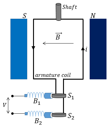
An electric generator consists of an armature coil $ABCD$ placed between two pole pieces of a magnet. The armature is connected to a shaft, which we can rotate mechanically. The ends of the armature coil are connected to 2 separate slip-rings ${S_1}$ and ${S_2}$ which are then connected to the output terminals through a pair of brushes ${B_1}$ and${B_2}$.
Due to the magnetic field from the Field magnets, there would be a flux linked with the coil. If $\theta $ is the angle between the area vector $\vec A$ of the coil and the magnetic field$\vec B$, then the flux linked with the coil is given as:
$\phi = \vec B \cdot \vec A = B\;Acos\theta $
Now, to generate emf in the coil, we rotate the coil using an external force. When the coil turns, the effective exposed area changes as the value $\theta $ changes.
If we assume that we are turning the shaft at a constant angular velocity $\omega $, then the angle $\theta $ at any instant would be:
$\theta = \omega \;t$
Now, we know from Faraday's law that the induced emf when the flux changes is given by:
$V = - \dfrac{{d\phi }}{{dt}}$
Here we can substitute the value of $\phi $ and $\theta $ to get how the emf produced is dependent on time.
$V = - \dfrac{{d\left( {B\;Acos\theta } \right)}}{{dt}} = - \dfrac{{d\left( {B\;Acos(\omega t)} \right)}}{{dt}}$
$V = B\;A\;\omega sin(\omega t)$
Thus, we can generate an ac power supply by rotating the generator at a constant angular velocity.
The brushes are used because, If the slip rings were tightly connected to the output, as the coil rotates, the wires would get twisted and eventually fail. A brush has a conducting carbon tip that provides a sliding contact between slip rings and terminals.
Note:
It seems that for a given $\omega$ of rotation, V is constant and hence, we can connect any low Resistance $R$ across the output and generate enormous power. But we know that this is against the law of Conservation of energy. With lower and lower resistance, the current in the coil also increases. We know that a current-carrying conductor placed in a magnetic field experiences a force given as $F = I\;l\;B$ where $I$ is the current, $l$ the length of wire and $B$ the magnetic field strength. So as the current increases, this force also increases, making it harder and harder to maintain a constant angular velocity. Thus, to get more output power, we have to apply more force on the shaft and the energy is always conserved.
Complete step by step answer:
An electric generator is a device capable of converting mechanical energy into electrical energy. It works on the principle of electromagnetic induction, which states that if the magnetic flux associated with a coil changes, an emf is induced in the coil.
An electric generator consists of an armature coil $ABCD$ placed between two pole pieces of a magnet. The armature is connected to a shaft, which we can rotate mechanically. The ends of the armature coil are connected to 2 separate slip-rings ${S_1}$ and ${S_2}$ which are then connected to the output terminals through a pair of brushes ${B_1}$ and${B_2}$.
Due to the magnetic field from the Field magnets, there would be a flux linked with the coil. If $\theta $ is the angle between the area vector $\vec A$ of the coil and the magnetic field$\vec B$, then the flux linked with the coil is given as:
$\phi = \vec B \cdot \vec A = B\;Acos\theta $
Now, to generate emf in the coil, we rotate the coil using an external force. When the coil turns, the effective exposed area changes as the value $\theta $ changes.
If we assume that we are turning the shaft at a constant angular velocity $\omega $, then the angle $\theta $ at any instant would be:
$\theta = \omega \;t$
Now, we know from Faraday's law that the induced emf when the flux changes is given by:
$V = - \dfrac{{d\phi }}{{dt}}$
Here we can substitute the value of $\phi $ and $\theta $ to get how the emf produced is dependent on time.
$V = - \dfrac{{d\left( {B\;Acos\theta } \right)}}{{dt}} = - \dfrac{{d\left( {B\;Acos(\omega t)} \right)}}{{dt}}$
$V = B\;A\;\omega sin(\omega t)$
Thus, we can generate an ac power supply by rotating the generator at a constant angular velocity.
The brushes are used because, If the slip rings were tightly connected to the output, as the coil rotates, the wires would get twisted and eventually fail. A brush has a conducting carbon tip that provides a sliding contact between slip rings and terminals.
Note:
It seems that for a given $\omega$ of rotation, V is constant and hence, we can connect any low Resistance $R$ across the output and generate enormous power. But we know that this is against the law of Conservation of energy. With lower and lower resistance, the current in the coil also increases. We know that a current-carrying conductor placed in a magnetic field experiences a force given as $F = I\;l\;B$ where $I$ is the current, $l$ the length of wire and $B$ the magnetic field strength. So as the current increases, this force also increases, making it harder and harder to maintain a constant angular velocity. Thus, to get more output power, we have to apply more force on the shaft and the energy is always conserved.
Recently Updated Pages
Master Class 12 Social Science: Engaging Questions & Answers for Success
Master Class 12 Physics: Engaging Questions & Answers for Success
Master Class 12 Maths: Engaging Questions & Answers for Success
Master Class 12 Economics: Engaging Questions & Answers for Success
Master Class 12 Chemistry: Engaging Questions & Answers for Success
Master Class 12 Business Studies: Engaging Questions & Answers for Success
Trending doubts
Which are the Top 10 Largest Countries of the World?
Draw a labelled sketch of the human eye class 12 physics CBSE
Explain the structure of megasporangium class 12 biology CBSE
What are the major means of transport Explain each class 12 social science CBSE
How many chromosomes are found in human ovum a 46 b class 12 biology CBSE
The diagram of the section of a maize grain is given class 12 biology CBSE