


Draw the circuit diagram of a summing amplifier using an operational amplifier.
Answer
614.7k+ views
Hint: The schematic representation of an electrical circuit is a circuit diagram. A pictorial circuit diagram generally uses component images. Basically, the summing amplifier is indeed an op-amp circuit which can merge input signal quantities into a single output which is the weighted sum of the inputs added.
Complete step by step solution:
Summing amplifier: Another type of operational amplifier circuit design used to integrate the voltages found on two or more inputs into a common output voltage is the Summing Amplifier.
The inverting amplifier does have a single voltage input (\[{V_{{\text{in}}}}\]) that is applied to the inverting terminal input. If we introduce more input resistors to the input, each equivalent in value to the initial input resistor (\[{R_{{\text{in}}}}\]), then we end up with another operating power amplifier termed the summing amplifier.
Operational amplifier: One of the fundamental building blocks of Analog Electronic Circuits is the operational amplifiers or Op-amps as they are more generally called. An operating amplifier or op-amp is a mechanism for voltage amplification intended to be used among its output and input terminals with external feedback elements, such as resistors and capacitors.
The circuit diagram of a summing amplifier using an operational amplifier is shown below:
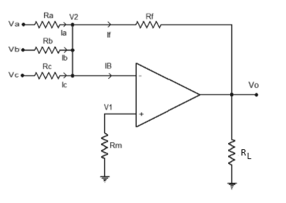
Here,\[{v_a}\],\[{v_b}\] and \[{v_c}\] are input voltages.
\[{R_a}\], \[{R_b}\], \[{R_c}\] are respective input resistors.
\[{I_a}\], \[{I_b}\] and \[{I_c}\] are currents.
\[{V_{\text{O}}}\]is the output voltage,
Note: In order to draw the circuit diagram we need to know what is circuit diagram and what components are required in order to define and draw the structure.
An Operating Amplifier is effectively a three-terminal unit containing two high impedance inputs. Each of the inputs is called Inverting Input. Other input is termed as non-inverting Input, labelled with a positive sign.
A summing amplifier with multiple resistors at the inputs produces a weighted sum. This is used in a digital-to-analogue converter to transform a binary number to a voltage. A summing amplifier is used in conjunction with an AC signal voltage to add a DC offset voltage.
Complete step by step solution:
Summing amplifier: Another type of operational amplifier circuit design used to integrate the voltages found on two or more inputs into a common output voltage is the Summing Amplifier.
The inverting amplifier does have a single voltage input (\[{V_{{\text{in}}}}\]) that is applied to the inverting terminal input. If we introduce more input resistors to the input, each equivalent in value to the initial input resistor (\[{R_{{\text{in}}}}\]), then we end up with another operating power amplifier termed the summing amplifier.
Operational amplifier: One of the fundamental building blocks of Analog Electronic Circuits is the operational amplifiers or Op-amps as they are more generally called. An operating amplifier or op-amp is a mechanism for voltage amplification intended to be used among its output and input terminals with external feedback elements, such as resistors and capacitors.
The circuit diagram of a summing amplifier using an operational amplifier is shown below:
Here,\[{v_a}\],\[{v_b}\] and \[{v_c}\] are input voltages.
\[{R_a}\], \[{R_b}\], \[{R_c}\] are respective input resistors.
\[{I_a}\], \[{I_b}\] and \[{I_c}\] are currents.
\[{V_{\text{O}}}\]is the output voltage,
Note: In order to draw the circuit diagram we need to know what is circuit diagram and what components are required in order to define and draw the structure.
An Operating Amplifier is effectively a three-terminal unit containing two high impedance inputs. Each of the inputs is called Inverting Input. Other input is termed as non-inverting Input, labelled with a positive sign.
A summing amplifier with multiple resistors at the inputs produces a weighted sum. This is used in a digital-to-analogue converter to transform a binary number to a voltage. A summing amplifier is used in conjunction with an AC signal voltage to add a DC offset voltage.
Recently Updated Pages
Master Class 12 Business Studies: Engaging Questions & Answers for Success
Master Class 12 Biology: Engaging Questions & Answers for Success
Master Class 12 Chemistry: Engaging Questions & Answers for Success
Class 12 Question and Answer - Your Ultimate Solutions Guide
Master Class 11 Social Science: Engaging Questions & Answers for Success
Master Class 11 English: Engaging Questions & Answers for Success
Trending doubts
Which is more stable and why class 12 chemistry CBSE
Which are the Top 10 Largest Countries of the World?
Draw a labelled sketch of the human eye class 12 physics CBSE
Differentiate between homogeneous and heterogeneous class 12 chemistry CBSE
What are the major means of transport Explain each class 12 social science CBSE
Sulphuric acid is known as the king of acids State class 12 chemistry CBSE