


Draw the circuit diagram of a common emitter amplifier using n-p-n transistors. What is the phase difference between the input signal and the output signal? State two reasons why a common amplifier is preferred over a common base amplifier.
Answer
531.9k+ views
Hint: A transistor is a semiconductor device used to amplify or switch electronic signals and electrical power. The full form of n-p-n transistor is negative-positive-negative transistor. NPN transistors are a type of bipolar transistor with three layers that are used for signal amplification.
Complete answer:
Emitter terminal is the heavily doped region as compared to two base and collector. This is because the work of the emitter is to supply charge carriers to the collector via the base. A common emitter amplifier is also known as a CE amplifier. The common emitter amplifier is a three basic single-stage bipolar junction transistor and is used as a voltage amplifier.
The circuit diagram of a common emitter amplifier using n-p-n transistor:
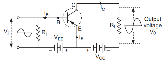
The phase difference between the two electrical quantities is defined as the angular phase difference between the maximum possible value of the two alternating quantities having the same frequency. In a common emitter amplifier using n-p-n transistors, the input and the output signal are in an opposite phase. This means that the phase difference between them is ${180^ \circ }$.
The two reasons why a common amplifier is preferred over a common base amplifier are:
(A) Voltage gain is uniform over a wide frequency range or power gain is high.
(B) Voltage gain is quite high without any phase change of signal voltage.
Note:
One more disadvantage of common base amplifiers is that in the common base amplifier configuration, the input current exceeds all other currents in the circuit, including the output current. The current gain of a common base amplifier is less than 1. We can also say that it attenuates current rather than amplifying it.
Complete answer:
Emitter terminal is the heavily doped region as compared to two base and collector. This is because the work of the emitter is to supply charge carriers to the collector via the base. A common emitter amplifier is also known as a CE amplifier. The common emitter amplifier is a three basic single-stage bipolar junction transistor and is used as a voltage amplifier.
The circuit diagram of a common emitter amplifier using n-p-n transistor:
The phase difference between the two electrical quantities is defined as the angular phase difference between the maximum possible value of the two alternating quantities having the same frequency. In a common emitter amplifier using n-p-n transistors, the input and the output signal are in an opposite phase. This means that the phase difference between them is ${180^ \circ }$.
The two reasons why a common amplifier is preferred over a common base amplifier are:
(A) Voltage gain is uniform over a wide frequency range or power gain is high.
(B) Voltage gain is quite high without any phase change of signal voltage.
Note:
One more disadvantage of common base amplifiers is that in the common base amplifier configuration, the input current exceeds all other currents in the circuit, including the output current. The current gain of a common base amplifier is less than 1. We can also say that it attenuates current rather than amplifying it.
Recently Updated Pages
Master Class 12 Business Studies: Engaging Questions & Answers for Success
Master Class 12 Chemistry: Engaging Questions & Answers for Success
Master Class 12 Biology: Engaging Questions & Answers for Success
Class 12 Question and Answer - Your Ultimate Solutions Guide
Master Class 11 English: Engaging Questions & Answers for Success
Master Class 11 Social Science: Engaging Questions & Answers for Success
Trending doubts
Which are the Top 10 Largest Countries of the World?
Draw a labelled sketch of the human eye class 12 physics CBSE
The end of compass needle which points towards north class 12 physics CBSE
Differentiate between homogeneous and heterogeneous class 12 chemistry CBSE
Why is the cell called the structural and functional class 12 biology CBSE
When was the first election held in India a 194748 class 12 sst CBSE